Shaping machine of vertical cement tube

A tube forming machine and cement technology, which is applied to ceramic forming machines, manufacturing tools, molds, etc., can solve the problems of low production efficiency and affect production costs, and achieve the effect of simple structure and ensuring working life.

Active Publication Date: 2006-06-14
张平
View PDF0 Cites 14 Cited by
  • Summary
  • Abstract
  • Description
  • Claims
  • Application Information

AI Technical Summary

Problems solved by technology

Since this is an intermittent cement pipe making process, the production efficiency is low, which seriously affects the production cost

Method used


Image

  • Shaping machine of vertical cement tube
  • Shaping machine of vertical cement tube
  • Shaping machine of vertical cement tube

Examples


Embodiment Construction

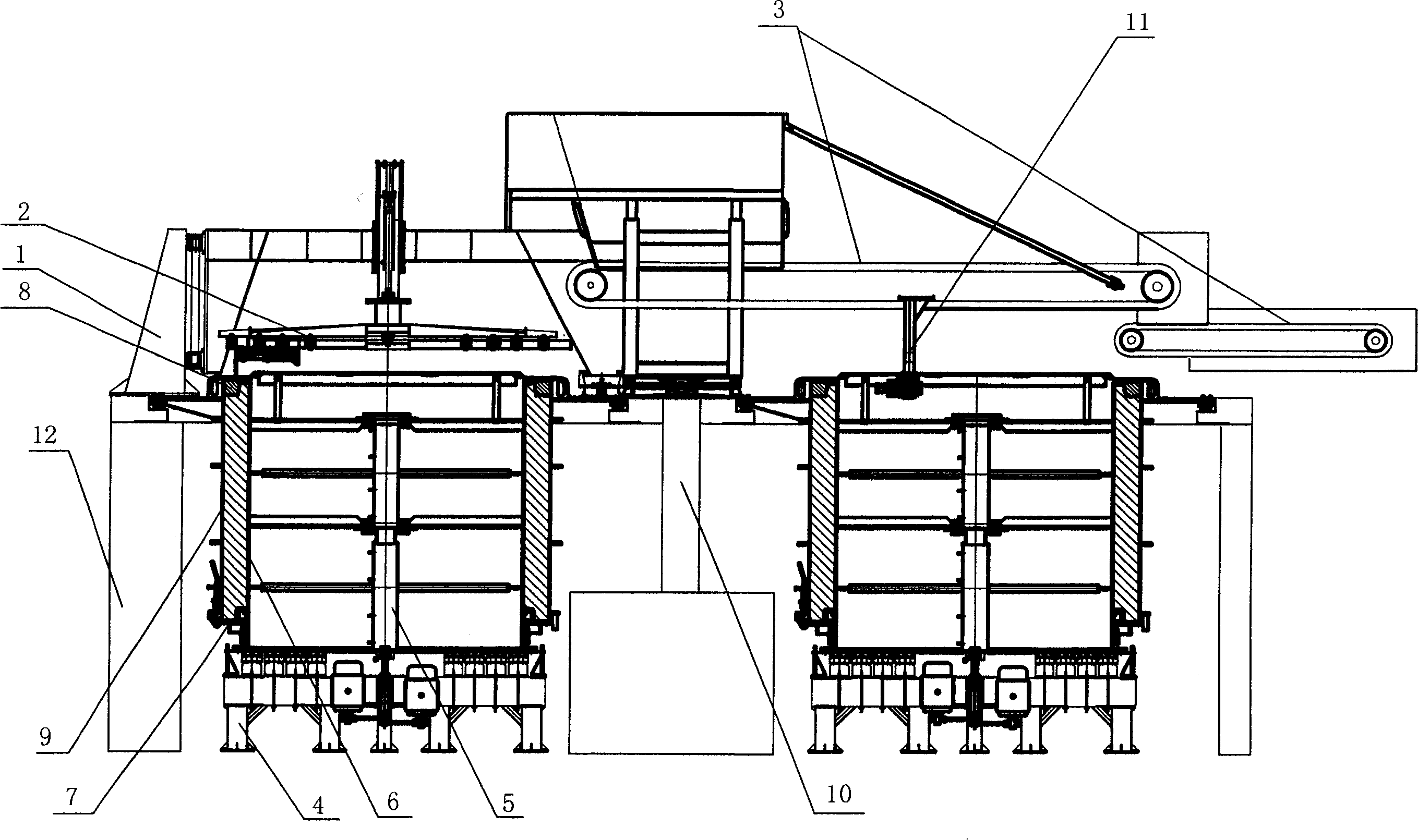
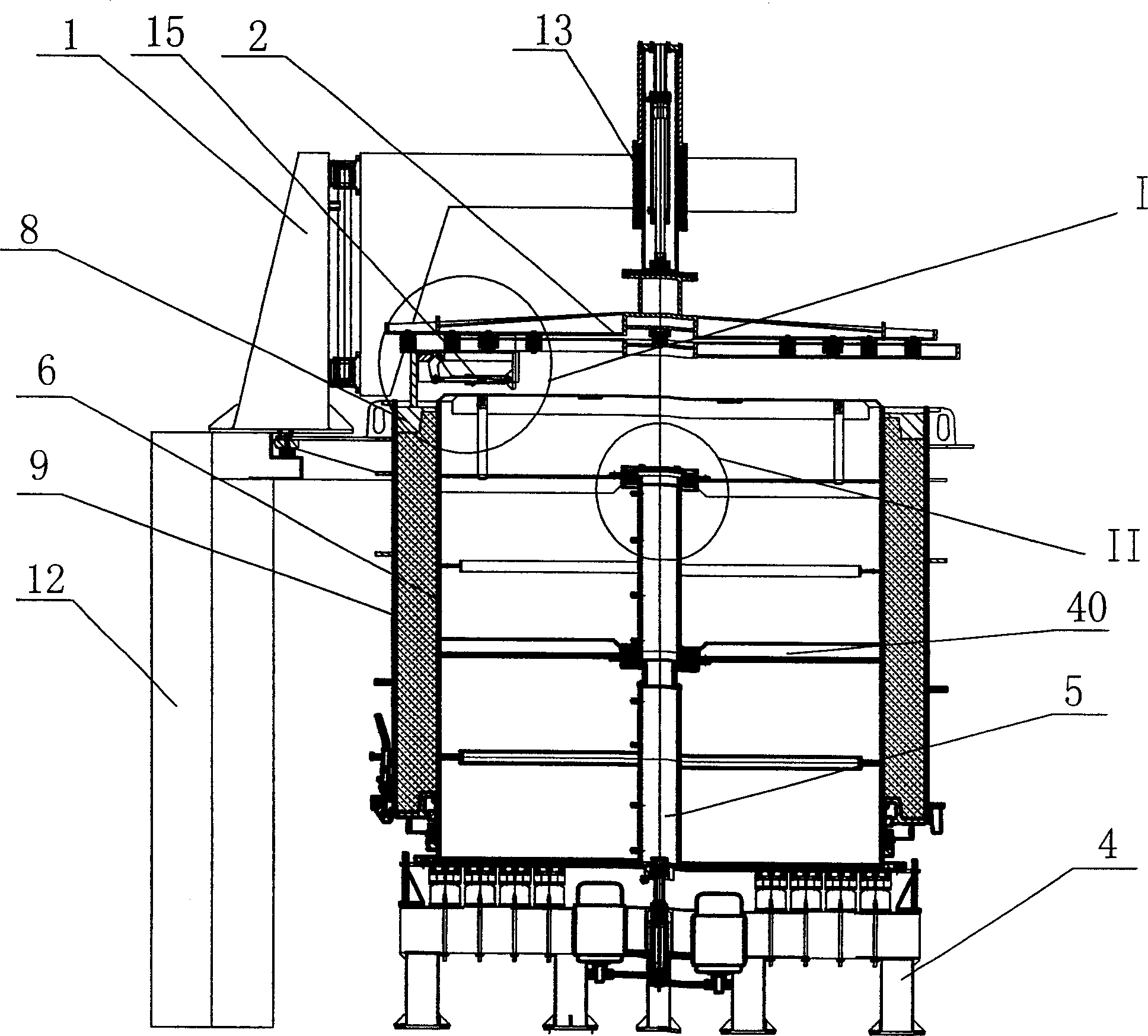
[0021] Depend on figure 1 It can be seen that the cement pipe forming machine includes a frame 12 and two sets of bases 4, on each set of bases 4, a concentric inner mold 6, an outer mold 9 and a vibrating mandrel 5 are arranged respectively, between the outer mold 9 and the inner mold 6 A socket forming die 7 is arranged at the annular bottom formed between the two, and a socket forming die 8 is arranged at the annular upper part formed between the outer die 9 and the inner die 6 . Set up a group of door frames 1 outside each group of machine bases 4, and set a set of die frames 2 on each group of door frames 1, and a feeding device composed of a conveyor belt 3 and a walking mechanism 11 is fixed on the frame 12. , the feeding device can rotate around the support column 10 under the action of the traveling mechanism 11 .

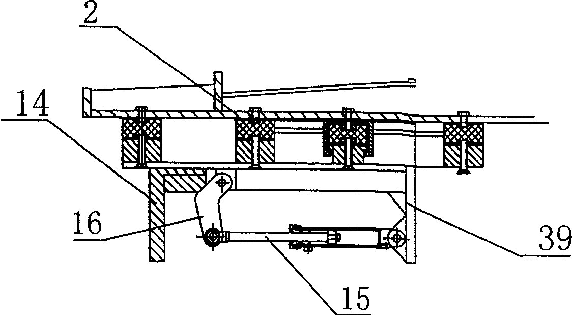
[0022] Such as figure 2 , 3 As shown, the door frame 1 is connected with a vertically telescopic oil cylinder 13, and the lower end of the oil cylinde...


PUM


Abstract

A vertical cement pipe forming machine is composed of base, a set of feeding unit consisting of conveying belt and walking mechanism and at least two sets of forming units. Each forming unit consists of machine frame, concentric internal mould, external mould and vibrating mandrel, shaping dies, and die pressing frame.

Description

technical field [0001] The invention relates to a cement pipe manufacturing technology, especially its equipment. Background technique [0002] In order to manufacture long cement pipes, the general vertical cement pipe making machine is composed of a vibrating mandrel fixed on the frame, an inner mold and an outer mold arranged on the periphery of the vibrating mandrel, and a door frame is arranged outside the machine base. A set of die frame is arranged on the door frame, and a feeding device is arranged on the frame. The concrete is fed into the inner and outer molds by the feeding device, and the feeding is stopped. Under the action of the vibrating mandrel, the concrete is vibrated and formed, and then the vibrated concrete and the inner and outer molds are lifted together by the die holder, and then steamed. Keep stereotypes. Since this is an intermittent cement pipe making process, the production efficiency is low, which seriously affects the production cost. Cont...

Claims


Application Information

Patent Timeline
IPC IPC(8): B28B21/16B28B21/76B28B21/90
Inventor 张平
Owner 张平
Why Eureka
Try Eureka