Improved mixer for a plasticizing screw

A technology of plasticizing screw and mixing part, applied in the field of plasticizing screw, can solve the problems of high cost and increase the space requirement of injection molding device, etc.

Inactive Publication Date: 2006-06-14
HUSKY INJECTION MOLDING SYST LTD
View PDF10 Cites 19 Cited by
  • Summary
  • Abstract
  • Description
  • Claims
  • Application Information

AI Technical Summary

Problems solved by technology

[0013] While it is possible to overcome these issues by increasing screw throughput by using larger or longer screws, this approach is expensive to actually implement and increases the space requirements of the injection molding unit

Method used


Image

  • Improved mixer for a plasticizing screw
  • Improved mixer for a plasticizing screw
  • Improved mixer for a plasticizing screw

Examples


Embodiment Construction

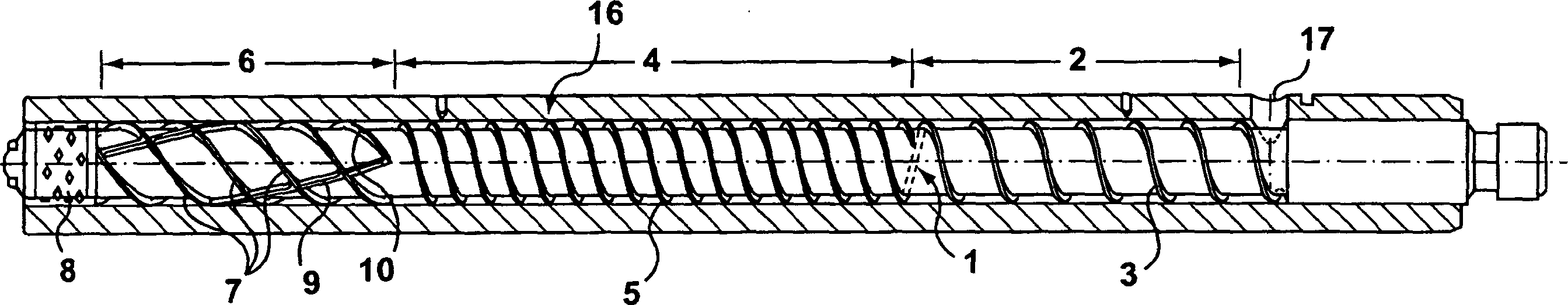
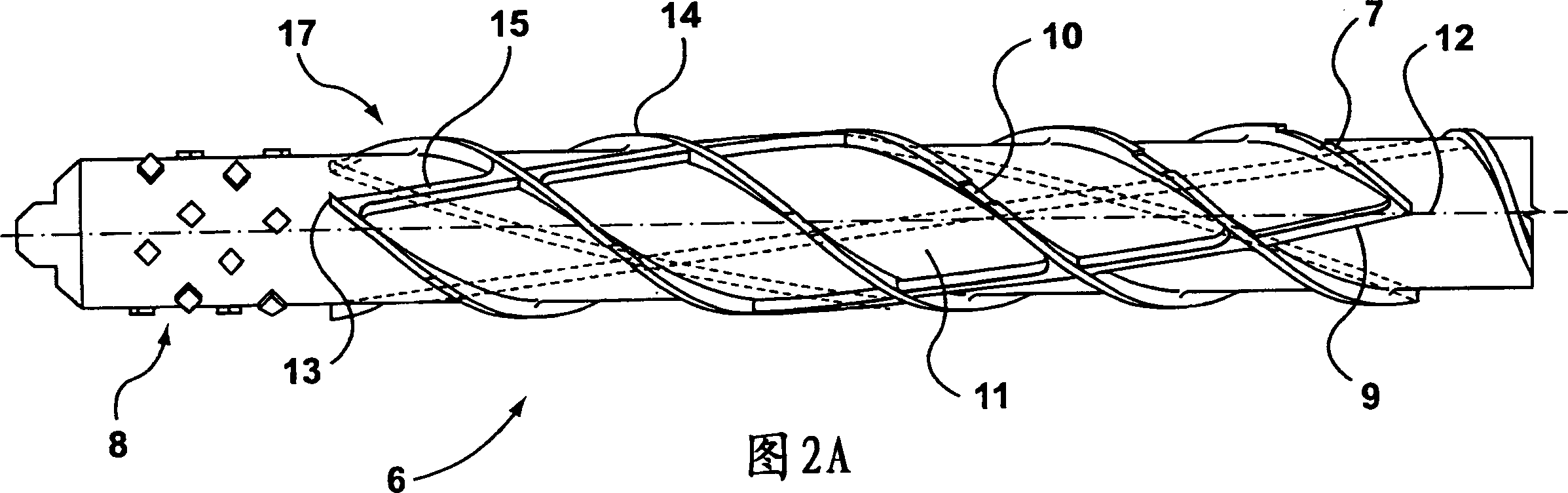
[0021] figure 1 Shown is a plasticizing screw 1 with an improved mixing section 6 provided by the invention. The screw 1 is located in the heating tube 16 . The heating tube 16 has an inlet 17 and an outlet (not shown) at one end of the tube 16 . The screw 1 consists of a feed section 2, a compression section 4, an improved mixing section 6 and a "pineapple" mixer 8 at the top of the screw, wherein the feed section 2 has a single conveying section 3 and the compression section has a double Delivery section 5. In the embodiment shown, the mixing section 6 comprises a triple delivery section 7 with some cutouts 10 and a triple counter-helical overflow section 9 acting as a baffle. The overflow section 9 prevents solid material from moving along the trough formed by the conveying section 7 . The cuts 10 in the section 7 allow for a better mixing of the molten material in the conveying section 7 .

[0022] The feeding part and compression part of the screw adopt the tradition...


PUM


Abstract

The invention provides an improved mixer section for a screw for a molding machine. The improved mixer section includes at least one conveying flight (7) and at least one spill flight (9) intersecting with the conveying flight(7) . At 1 east one notch (10) is formed in the conveying flight (7) to enable mixing between adjacent flow channels (18) . The spill flight (9) terminates near the output of the mixer to create a trap zone for any unmelts that reach that area of the mixer.

Description

technical field [0001] The present invention relates to a plasticizing screw for high production injection molding machinery with unique characteristics for melting and mixing resin. Background technique [0002] There are a wide variety of plasticizing screws used to plasticize plastic resins. Designs that include mixing features as well as features for separating melt from unmelt are relevant to the present invention. [0003] US Patent No. 4,330,214 to Willert teaches a plasticizing screw having a feed zone, a plasticizing zone and a metering zone. A second section is introduced halfway along the screw to separate the molten material from the unmelted material. The melt pool floods the overflow section and accumulates in the progressively deeper trough between the overflow section and the downstream conveying section, while the unmelted material remains in the progressively shallower trough between the overflow section and the downstream conveying section. Between upst...

Claims


Application Information

Patent Timeline
Patent Type & Authority Applications(China)
IPC IPC(8): B29C45/47B29C45/54B29C45/60B29C48/03B29C48/53B29C48/65B29C48/67
CPCB29C45/47B29C48/03B29C48/53B29C48/65
Inventor 雷蒙德·W·张丹尼斯·D·克雷格
Owner HUSKY INJECTION MOLDING SYST LTD
Why Eureka
Try Eureka