Apparatus and method for detecting and monitoring displacement/deflection

A monitoring device and displacement technology, applied in measurement devices, optical devices, instruments, etc., can solve the problems of restricting promotion and application, high requirements for operation and adjustment, difficult installation and debugging, etc., to achieve convenient transmission and processing, and low manufacturing costs. , the effect of simple structure

Inactive Publication Date: 2006-06-21
CHONGQING JIAOTONG UNIVERSITY
View PDF2 Cites 55 Cited by
  • Summary
  • Abstract
  • Description
  • Claims
  • Application Information

AI Technical Summary

Benefits of technology

This technology uses an optical system called Laserscope (a type of specialized instrument) to measure movements along different directions. By measuring these movements over space, this technology allows researches like identifying patterns caused by earthquake activity without physically moving equipment around them. Additionally, there have been previous inventions related to analyzing large amounts of data about geology during construction work. These improvements make the process more efficient than traditional methods such as surveying techniques.

Problems solved by technology

This patents describes various ways to measure changes over time caused due to factors like tunneling or underground movements during construction projects. These measurements require precise location data acquisition (GPS) technology along with accurate tracking systems. However, existing techniques have limitations in terms of accuracy and ease of implementation across multiple platforms.

Method used


Image

  • Apparatus and method for detecting and monitoring displacement/deflection
  • Apparatus and method for detecting and monitoring displacement/deflection
  • Apparatus and method for detecting and monitoring displacement/deflection

Examples


Embodiment Construction

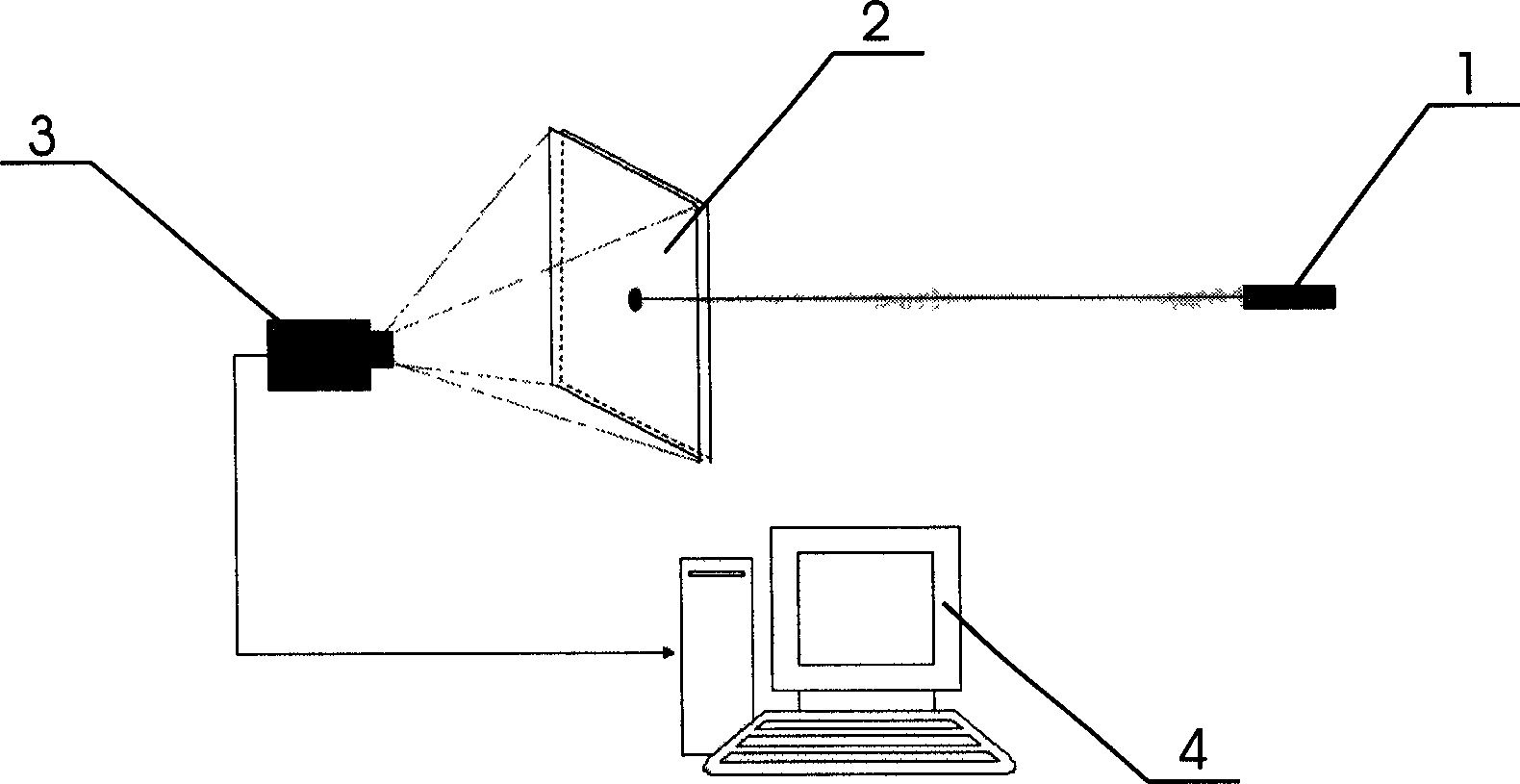
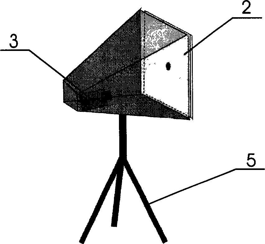
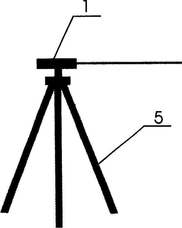
[0020] figure 1 As shown, the displacement / deflection detection and monitoring device of the present invention is composed of a laser transmitter 1, a semi-reflective projection panel 2, an imaging device 3 and a computer 4 with pre-installed corresponding software; the imaging device 3 is connected with the computer 4 through a circuit, and the imaging device 3 is provided with a semi-reflective projection panel 2 at the lens end; the laser emitter 1 is arranged at the point to be measured, and the laser emitter 1 and the semi-reflective projection panel 2 are adjusted according to the reflected light beam so that the laser emission direction is aligned with the semi-reflective projection panel 2, and It is well perpendicular to the semi-reflective projection panel 2 .

[0021] When working, the laser emitter 1 emits laser light and projects it onto the semi-reflective projection panel 2 which is far away and placed at a fixed point. When the point to be measured is displace...


PUM


Abstract

The invention discloses a displacement-deflection detecting and monitoring device and method, which comprises the following parts: laser launcher, receiving disposal device and software presetting computer, wherein the receiving disposal device is composed of image equipment and image panel; the image equipment connects the computer through circuit; the projection panel is set in the lens end of image equipment; the laser launcher is set in the reference detected point, which aligns the projection panel of receiving disposal device to keep the projection panel and laser beam basically vertical; the precision staff scale film is attached on the back of semi-reflection projection face; when the detected point moves, the projected laser flare offsets on the projection panel simultaneously; the image equipment picks up the flare signal and sends the signal to the computer, which counts the displacement with respect to the zero point. The invention is fit for detecting and monitoring the bridge deflection, ground sedimentation, mountain shift, building subsidence and shift.

Description


Claims


Application Information

Patent Timeline
Owner CHONGQING JIAOTONG UNIVERSITY
Why Eureka
Try Eureka