

Plasma display panel
A plasma display panel and electrode technology, applied in the direction of AC plasma display panels, discharge tubes, addressing electrodes, etc., can solve problems such as brightness deviation and achieve the effect of reducing brightness deviation
- Summary
- Abstract
- Description
- Claims
- Application Information
AI Technical Summary
Problems solved by technology
Method used
Image

Examples
no. 1 example
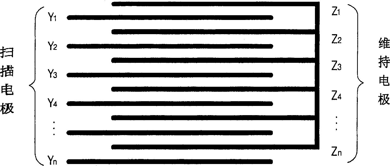
[0069] Figure 7 The electrodes of the plasma display panel according to the first embodiment of the present invention are shown. like Figure 7 As shown, in the electrode structure of the plasma display panel according to the first embodiment of the present invention, scan electrodes, sustain electrodes, and scan electrodes are sequentially formed.
[0070] Therefore, two scan electrodes and one sustain electrode form two sustain electrode pairs. For example, the second scan electrode Y 2 and the second sustain electrode Z 2 A sustain electrode pair is formed, and the third scan electrode Y 3 and the second sustain electrode Z 2 A sustain electrode pair is formed. Therefore, with the help of the second scan electrode Y 2 and the second sustain electrode Z 2 Instead, pulses are supplied to the discharge cells. With the help of the third scan electrode Y 3 and the second sustain electrode Z 2 Instead, pulses are supplied to the discharge cells.
[0071] The sustain ...
no. 2 example
[0081] Figure 9 An electrode of a plasma display panel according to a second embodiment of the present invention is shown. In the second embodiment of the present invention, the width of the sustain electrodes is the same as that of the scan electrodes and the thickness of the sustain electrodes is greater than that of the scan electrodes.
[0082] like Figure 9 As shown, in the electrode structure of the plasma display panel according to the second embodiment of the present invention, scan electrodes, sustain electrodes, and scan electrodes are sequentially formed.
[0083] Therefore, two scan electrodes and one sustain electrode form two sustain electrode pairs. For example, the second scan electrode Y 2 and the second sustain electrode Z 2 A sustain electrode pair is formed, and the third scan electrode Y 3 and the second sustain electrode Z 2 Another sustain electrode pair is formed.
[0084] The sustain electrodes and the scan electrodes are formed of the same ma...
no. 3 example
[0096] Figure 11 An electrode of a plasma display panel according to a third embodiment of the present invention is shown. In the third embodiment of the present invention, the sustain electrodes have the same width and thickness as the scan electrodes, and the resistivity of the material forming the sustain electrodes is smaller than the resistivity of the material forming the scan electrodes.
[0097] like Figure 11 As shown, in the electrode structure of the plasma display panel according to the third embodiment of the present invention, scan electrodes, sustain electrodes, and scan electrodes are sequentially formed.
[0098] Therefore, two scan electrodes and one sustain electrode form two sustain electrode pairs. For example, the second scan electrode Y 2 and the second sustain electrode Z 2 A sustain electrode pair is formed, and the third scan electrode Y 3 and the second sustain electrode Z 2 Another sustain electrode pair is formed.
[0099] In the electrode...
PUM
 Abstract
Description
Claims
Application Information