Linear motor

A linear motor and polarity technology, applied in the direction of magnetic circuit shape/style/structure, magnetic circuit static parts, electrical components, etc., to achieve the effect of avoiding magnetic leakage and excess heat release, and preventing direct contact

Inactive Publication Date: 2006-06-21
FANUC LTD
View PDF1 Cites 8 Cited by
  • Summary
  • Abstract
  • Description
  • Claims
  • Application Information

AI Technical Summary

Problems solved by technology

However, when the external force applied to the excitation part is very large, the impact permanent magnet may be separated from the magnetic plate.

Method used


Image

  • Linear motor
  • Linear motor
  • Linear motor

Examples


Embodiment Construction

[0031] Embodiments of the present invention will be described below with reference to the drawings. In the following figures, the same parts are marked with the same symbols. The figures are appropriately scaled down for ease of understanding.

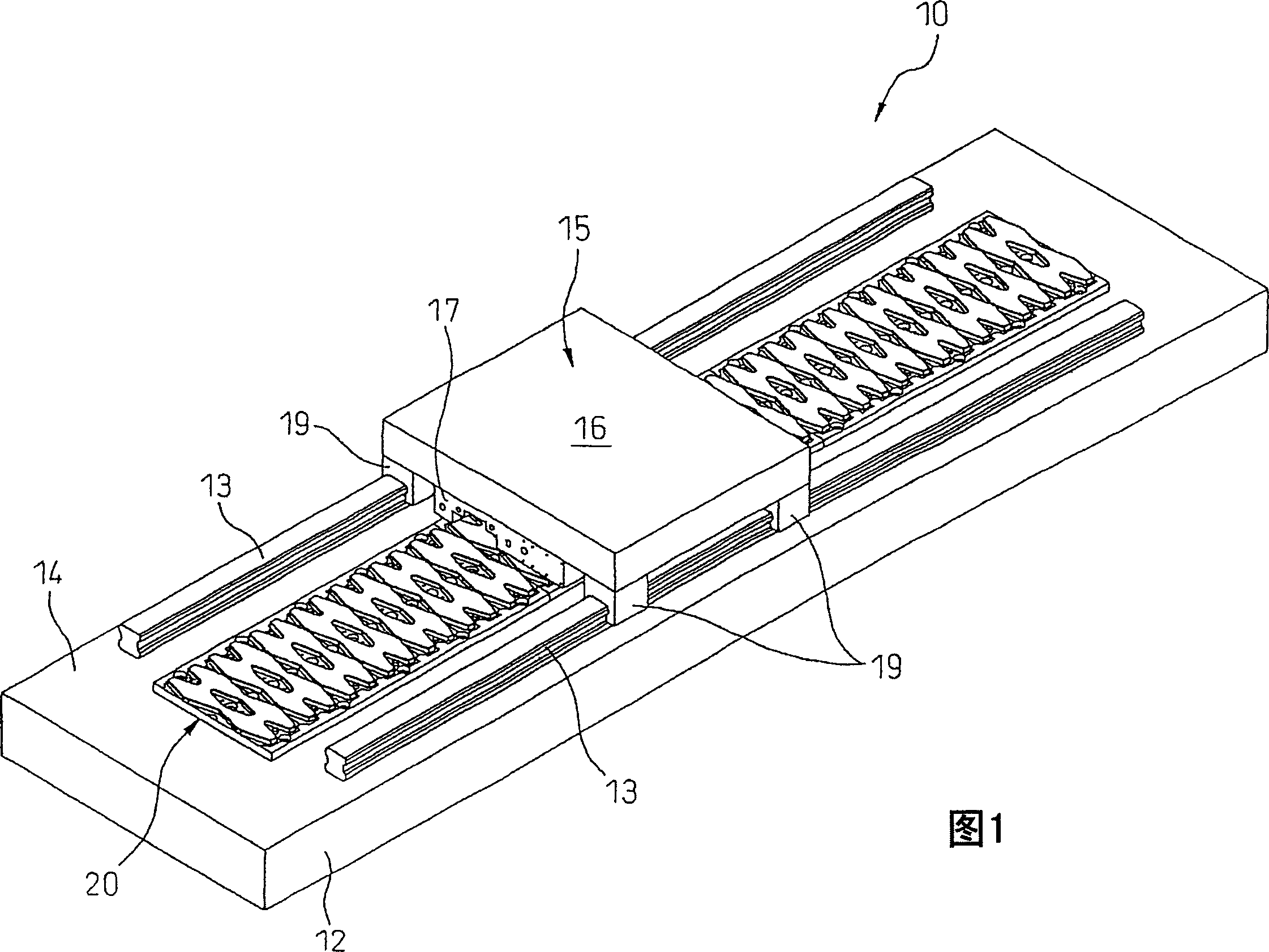
[0032] FIG. 1 is a perspective view of a linear motor according to the present invention. As shown in FIG. 1 , a linear motor 10 used in machine tools and the like is a linear synchronous motor in which an armature 15 is a movable member and a field yoke 20 is a stator. A field yoke 20 serving as a stator is provided on the surface 14 of the base 12 . Further, guide rails 13 extending parallel to the field yoke 20 are disposed on both sides of the base 12 .

[0033] The armature 15 includes a substantially rectangular parallelepiped armature core 16 made of laminates of a plurality of magnetic thin plate materials such as silicon steel sheets, and a plurality of narrow slots recessed substantially parallel to each other on one surfa...


PUM


Abstract

The present invention provides a linear motor (10) comprising an excitation part (20) and an armature (15) arranged with a predetermined interval to the excitation part and moving linearly along the excitation part. The excitation part includes a plate (21), A plurality of permanent magnets (24) arranged adjacent to each other with different polarities on the board and a mechanical fixing member (30) for mechanically fixing each of the permanent magnets to the board. In this way, the permanent magnets are prevented from detaching in the event of an external force being applied. The mechanical fixing member may also include a covering portion (31) covering the exposed surface of the permanent magnet, and the mechanical fixing member is preferably formed of a non-magnetic material or a weakly magnetic material.

Description

technical field [0001] The present invention relates to linear motors, for example, linear motors used for table feed of machine tools and the like. Background technique [0002] In recent years, linear motors, which are easy to drive at high speed and have excellent quietness, have been adopted as drive units of various industrial machines such as spindle / table feed mechanisms of machine tools and magnetic head drive mechanisms of OA machines. Among such linear motors, in many cases, permanent magnets are used in the excitation part in the linear DC motor and the linear synchronous motor to simplify the structure. [0003] As disclosed in Japanese Patent Application Laid-Open No. 8-186974, a permanent magnet excitation linear motor generally includes: an excitation part having a plurality of permanent magnets arranged in parallel on a plate; An armature of a coil that relatively moves linearly with respect to a plurality of permanent magnets in a direction sequentially acr...

Claims


Application Information

Patent Timeline
Patent Type & Authority Applications(China)
IPC IPC(8): H02K41/02H02K1/17
CPCH02K1/17H02K41/031
Inventor 曾我部正丰志村孔史
Owner FANUC LTD
Why Eureka
Try Eureka