Manufacturing method of model forming module and optical component

A molding and stamping technology, applied in manufacturing tools, glass pressing, glass manufacturing equipment, etc., can solve the problems of disappearance of main mold and upper mold, smaller sliding gap, deterioration of slope, etc., and achieve eccentric accuracy or wall thickness. High thickness accuracy, preventing mold breakage, and suppressing tipping effects

Active Publication Date: 2006-06-28
HOYA CORP
View PDF2 Cites 6 Cited by
  • Summary
  • Abstract
  • Description
  • Claims
  • Application Information

AI Technical Summary

Problems solved by technology

However, if it is carried out in the above-mentioned manner, there will be no butt joint between the flange of the upper mold and the top of the main mold, so the function of maintaining the coaxiality of the main mold and the upper mold will disappear.
That is, the upper mold tends to fall in the main mold within the allowable range due to sliding with the main mold, and in the formed lens, the inclination (inclination) of the first surface and the second surface deteriorates.
This is a problem for the above-mentioned lens that requires high precision, and cannot be avoided only by reducing the sliding gap

Method used


Image

  • Manufacturing method of model forming module and optical component
  • Manufacturing method of model forming module and optical component
  • Manufacturing method of model forming module and optical component

Examples


Embodiment Construction

[0044] Next, preferred embodiments of the present invention will be described with reference to the drawings.

[0045] (Compression molding die (first embodiment))

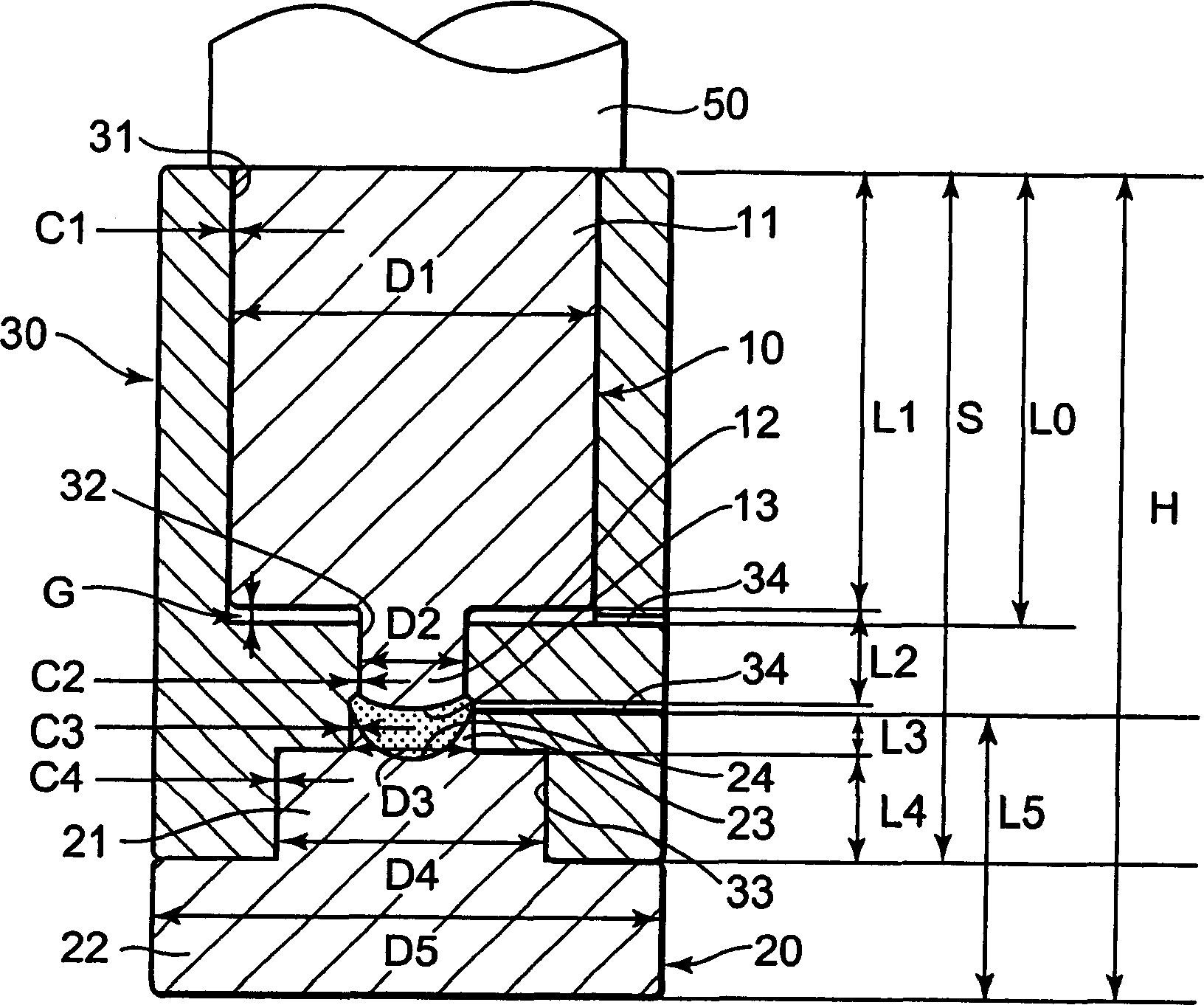
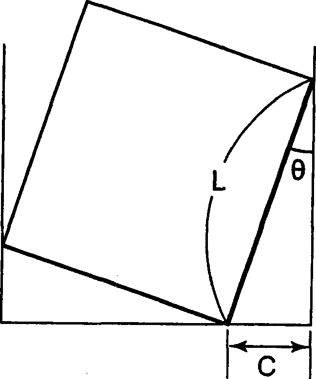
[0046] figure 1 is a cross-sectional view of a press molding die according to a first embodiment of the present invention, figure 2 It is a diagram showing the relationship between slide guide length, clearance and inclination.

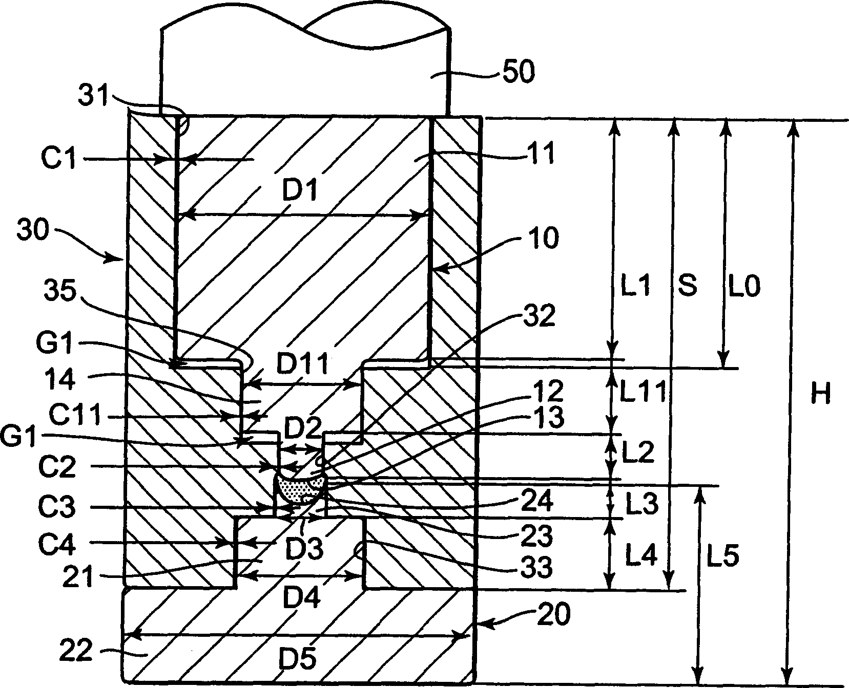
[0047] Such as figure 1 As shown, the compression molding die (hereinafter simply referred to as the forming die) is composed of an upper die 10 , a lower die 20 , and a main body die 30 .

[0048] The upper mold 10 and the lower mold 20 are used to press and shape the molding material (for example, a glass preform) 40 between the upper mold 10 and the lower mold 20, or to open ( Decomposition) forming mold can move up and down relative to main body mold 30.

[0049] In addition, in the molding die of the present embodiment, when press molding is formed by pressurizing a molding mat...


PUM


Abstract

When the axial length of the large-diameter portion 11 of the upper die (sliding die) (10) is defined as (L1), and the axial length of the small-diameter portion (12) of the upper die (10) is defined as (L2), L1>L2 is established, when the large diameter portion (21) of the lower mold (stationary mold) (20) is accommodated in the (2) inner peripheral large diameter portion (33) of the main body mold (30), when passing through the main mold (30) ) is docked with the flange portion (22) of the lower mold (20), the mutual position of the lower mold (20) and the main mold (30) is specified, and the upper mold (10) is slidably guided to the main mold ( When the length in the axial direction of the portion in 30) is (L), and the overall length in the axial direction of the main body (30) is (S), L≥0.5S holds.

Description

technical field [0001] The present invention relates to a molding die (mold press) for forming optical elements used in glass lenses and the like, especially optical pickups with extremely high eccentricity accuracy, compact imaging equipment, and the like, and a method for manufacturing the optical elements . Background technique [0002] There is known a method for manufacturing optical elements such as lenses by heating and softening molding materials such as glass, and then press-molding them with a pair of upper and lower molding dies that are precisely machined into a predetermined shape (for example, refer to Japanese Patent Laid-Open 2002 - Publication No. 29763 (Patent Document 1), Japanese Utility Model Publication No. 4-14429 (Patent Document 2).). [0003] Patent Document 1 describes a molding die for forming a microscope and the like with extremely small coma aberration. Here, the approach direction of the upper mold and the lower mold is restricted by the fir...

Claims


Application Information

Patent Timeline
Patent Type & Authority Applications(China)
IPC IPC(8): C03B11/00C03B11/08
CPCC03B11/08C03B2215/72Y02P40/57
Inventor 山越吉弘山下照夫泽田浩之
Owner HOYA CORP
Why Eureka
Try Eureka