Agitator, agitating method, and melting furnace with agitator

A technology of stirring device and melting furnace, which is applied in the direction of stirring device, furnace, furnace components, etc., can solve the problems of large capital investment, increased cost, high price, etc.

Inactive Publication Date: 2006-06-28
高桥谦三
View PDF0 Cites 17 Cited by
  • Summary
  • Abstract
  • Description
  • Claims
  • Application Information

AI Technical Summary

Problems solved by technology

In addition, although a coil is used to form a magnetic field, in order to suppress the oscillation of the coil, it must be cooled reliably. Not only must careful attention be paid to cooling, but the overall complexity of t

Method used


Image

  • Agitator, agitating method, and melting furnace with agitator
  • Agitator, agitating method, and melting furnace with agitator
  • Agitator, agitating method, and melting furnace with agitator

Examples


Embodiment Construction

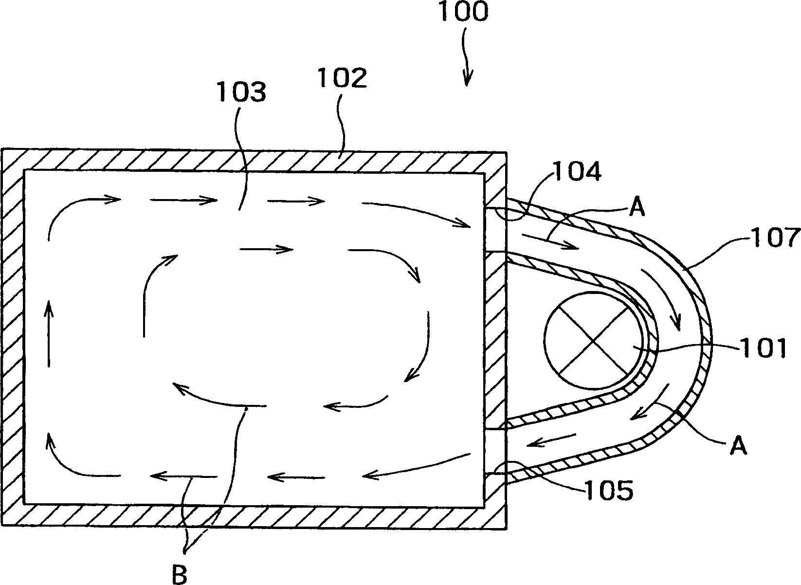
[0016] figure 1 The overall structure of the melting furnace system (melting furnace with stirring device) 100 incorporating the stirring device 101 according to the present invention is shown planarly. That is, an existing melting furnace can be used for the melting furnace (melting furnace main body) 102 . That is to say, this kind of melting furnace 102 is to put in blanks of non-ferrous metals such as aluminum (Al, Cu, Zn or alloys of at least two of them, or non-ferrous metals of conductors (conductors) such as Mg alloys), and pass through each A burner (not shown) heats and melts. In addition, the present invention can of course be applied to melting furnaces of other metals besides melting furnaces of non-ferrous metals. A melt outlet 104 and a melt inlet 105 are provided on one of the four side walls of the melting furnace 102 . The melt outlet 104 and the melt inlet 105 communicate through a melt passage member 107 made of a refractory material (or a heat-resistant...


PUM


Abstract

An agitator for agitating a melt includes a heat-resistive container having a blast opening through which cooling air is blown and an exhaust opening for exhausting air having been subjected to heat exchange, and a rotating magnet assembly composed of a permanent magnet housed in the heat-resistive container in a rotatable manner, magnetic lines of force emitted from the permanent magnet penetrating through the heat-resistive container to exit outside, and then penetrating the heat-resistive container again to return to the permanent magnet.

Description

technical field [0001] The invention relates to a stirring device and method, and a melting furnace with a stirring device using the stirring device. Background technique [0002] Conventionally, Al, Cu, Zn, or alloys of at least two of them, or scrap metals such as conductors (conductors) such as Mg alloys, etc., are dissolved, formed into billets, and commercialized. At this time, in order to make the quality of the billet uniform, the aluminum etc. in the melting furnace should be fully stirred. Therefore, a stirring rod is put into a melting furnace to artificially stir the molten aluminum or the like, or an electric stirring device is installed at the bottom of the furnace, and the molten aluminum or the like is stirred by the device. [0003] In the case of the above-mentioned artificial stirring in the prior art, it becomes the operation under the severe environment of ultra-high temperature, and the adverse effect on the operator cannot be ignored. Furthermore, in ...

Claims


Application Information

Patent Timeline
IPC IPC(8): F27B3/00B22D45/00F27D27/00
Inventor 高桥谦三
Owner 高桥谦三
Why Eureka
Try Eureka