Liquid crystal panel and liquid crystal display apparatus

A technology of liquid crystal panel and liquid crystal layer, which can be used in television, optics, instruments, etc., can solve the problems of not obtaining retardation film, film breakage, and small photoelastic coefficient, and achieve excellent display uniformity, prevent unevenness, and good display. The effect of uniformity

Active Publication Date: 2006-06-28
NITTO DENKO CORP
View PDF19 Cites 4 Cited by
  • Summary
  • Abstract
  • Description
  • Claims
  • Application Information

AI Technical Summary

Problems solved by technology

However, such a film hardly causes retardation, and a desired retardation value cannot be obtained by stretching at a low draw ratio, or even at a high draw ratio, as in an aromatic polymer film.
Stretching at high draw ratios causes problems with film rupture
Therefore, although a retardation film of an aliphatic resin film having a small photoelastic coefficient and nx≥ny≥nz has been obtained by the conventional technique (JP 2001-215332 A), a retardation film having a relationship of nx>nz>ny has not been obtained so far. Retardation film

Method used


Image

  • Liquid crystal panel and liquid crystal display apparatus
  • Liquid crystal panel and liquid crystal display apparatus
  • Liquid crystal panel and liquid crystal display apparatus

Examples


Embodiment 1

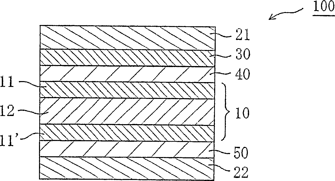
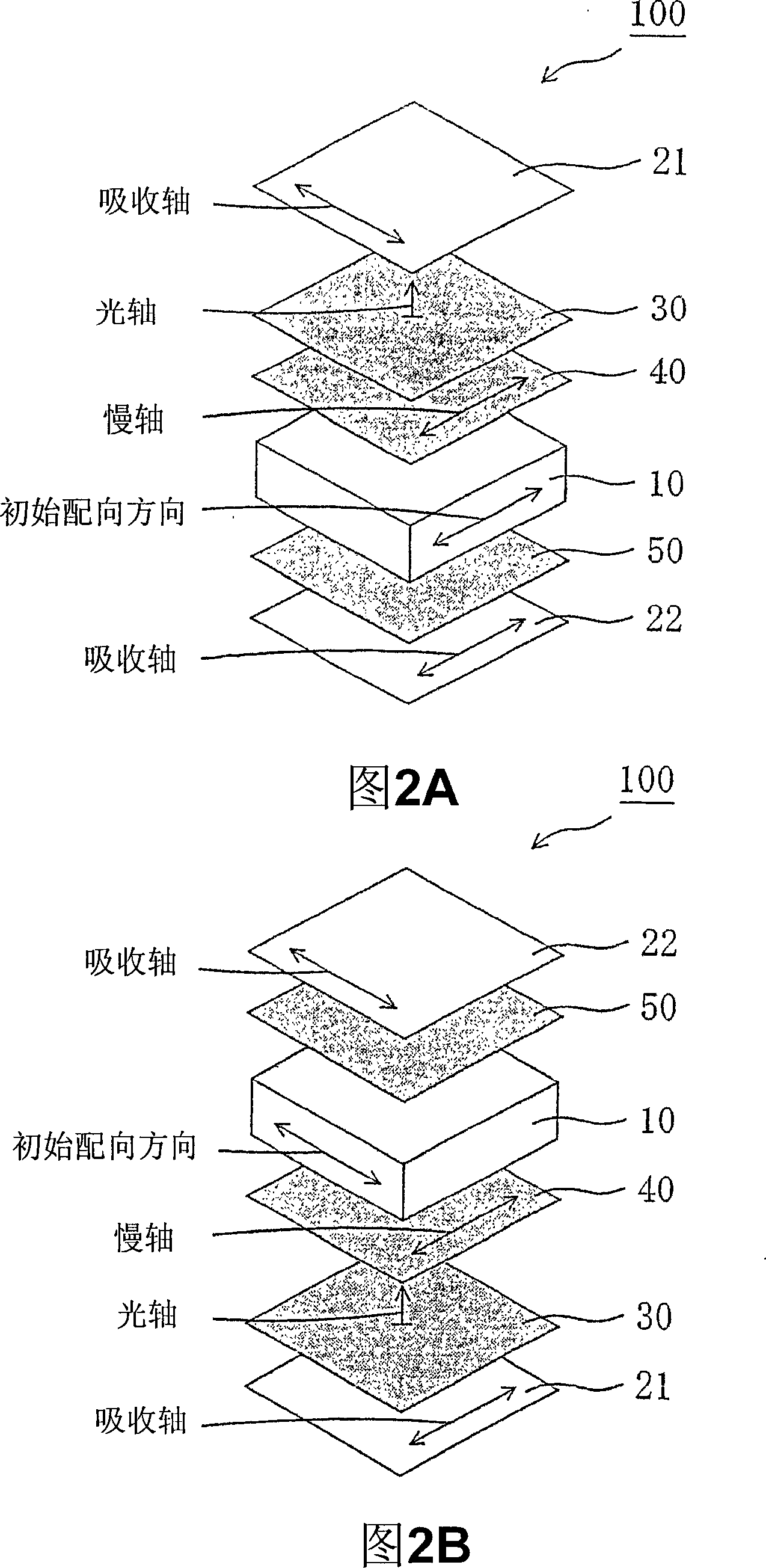
[0371] The retardation film 2-A obtained in Reference Example 4 was laminated as a second optical member on the viewing side of the liquid crystal cell obtained in Reference Example 12 through an acrylic pressure-sensitive adhesive layer (20 μm in thickness), so that The short sides of the liquid crystal cell and the slow axis of the retardation film 2-A are parallel to each other. Then, the retardation film 1-A obtained in Reference Example 2 was laminated as the first optical element on the surface of the retardation film 2-A through an acrylic pressure-sensitive adhesive layer (20 μm in thickness), so that the retardation film The slow axis of 2-A and the slow axis of retardation film 1-A are perpendicular to each other. Next, the polarizer P1 obtained in Reference Example 1 was passed through an adhesive layer "GOHSEFIMER Z200" (trade name, thickness 1 µm, Nippon Synthetic Chemical Industry Co. ., Ltd.) to be laminated on the surface of the retardation film 1-A so that th...

Embodiment 2

[0378] A liquid crystal panel B and a liquid crystal display device B were produced in the same manner as in Example 1, except that the optical film 3-C obtained in Reference Example 11 was used as a third optical element. As soon as the backlight is turned on, the LCD panel exhibits good display uniformity across the entire surface. Then, the backlight was turned on for 10 minutes, thereby measuring the contrast in the oblique direction and the color shift in the oblique direction. Tables 5 and 6 show the resulting properties. With the backlight turned on continuously for 2 hours, the display screen of the liquid crystal display device was photographed in a dark room with a two-dimensional color distribution measuring apparatus "CA-1500" (manufactured by Konica Minolta Holdings, Inc.). Such as Figure 7 As shown, slight display unevenness due to heat of the backlight was observed.

Embodiment 3

[0380] Produce liquid crystal panel C and liquid crystal display device C according to the same method as embodiment 1, except that the retardation film 1-B obtained in reference embodiment 3 is used as the first optical element, and the retardation film 2 obtained in reference embodiment 6 -C was used as the second optical element and the optical film 3-C obtained in Reference Example 11 was used as the third optical element. When the backlight is turned on, the liquid crystal panel exhibits good display uniformity across the entire surface. Then, the backlight was turned on for 10 minutes, thereby measuring the contrast in the oblique direction and the color shift in the oblique direction. Tables 5 and 6 show the resulting properties. With the backlight kept on for 2 hours, the display screen of the liquid crystal display device was photographed in a dark room with a two-dimensional color distribution measuring apparatus "CA-1500", manufactured by Konica Minolta Holdings, I...


PUM

PropertyMeasurementUnit
thicknessaaaaaaaaaa
thicknessaaaaaaaaaa
thicknessaaaaaaaaaa

Abstract

There is provided a liquid crystal panel having an improved contrast ratio in an oblique direction and an improved color shift in an oblique direction. Further, there is provided a liquid crystal panel with excellent display uniformity. The liquid crystal panel of the present invention includes: a liquid crystal cell; a first polarizer arranged on one side of the liquid crystal cell; a second polarizer arranged on the other side of the liquid crystal cell; a first optical element and a second optical element arranged between the first polarizer and the liquid crystal cell; and a third optical element arranged between the second polarizer and the liquid crystal cell, in which: the first optical element has substantially optically negative uniaxial property; the second optical element satisfies the following expressions (1) and (2) and is arranged between the first optical element and the liquid crystal cell; and the third optical element has substantially optical isotr.

Description

[0001] This application is based on U.S.C. 35 Part 119 and claims priority to Japanese Patent Application No. 2004-367040, filed December 20, 2004, and Japanese Patent Application No. 2005-190515, filed June 29, 2005, incorporated herein by Reference. technical field [0002] The invention relates to a liquid crystal panel with a liquid crystal unit, a polarizer and an optical element. Furthermore, the present invention relates to a liquid crystal television and a liquid crystal display device both using the liquid crystal panel. Background technique [0003] Liquid crystal display devices attract attention due to their properties such as thinness, lightness, and low power consumption, and are widely used in: portable equipment such as mobile phones and watches; office automation (OA) equipment such as personal computer monitors, laptop personal computers; and home appliances such as video cameras and LCD TVs. Due to technological innovation, the defects that the display p...

Claims


Application Information

Patent Timeline
Patent Type & Authority Applications(China)
IPC IPC(8): G02F1/1335G02F1/1333G02B5/30H04N5/00
Inventor 与田健治矢野周治林政毅
Owner NITTO DENKO CORP
Why Eureka
Try Eureka