Massage protection architecture in dust collector

A technology for protecting structures and buttons, applied in vacuum cleaners, cleaning equipment, household appliances, etc., can solve the problem of buttons being pressed by mistake, and achieve the effect of reducing the action stroke, realizing self-protection, and improving production efficiency.

Inactive Publication Date: 2006-07-05
LG ELECTRONICS (TIANJIN) APPLIANCES CO LTD
View PDF0 Cites 7 Cited by
  • Summary
  • Abstract
  • Description
  • Claims
  • Application Information

AI Technical Summary

Problems solved by technology

[0008] The present invention aims to solve the problem of keys with large surface areas being accidentally pressed in the prior art, an

Method used


Image

  • Massage protection architecture in dust collector
  • Massage protection architecture in dust collector
  • Massage protection architecture in dust collector

Examples


Example Embodiment

[0035] The present invention will be described in detail below with reference to the drawings and embodiments. Components with the same structure in the drawings use the same symbols.
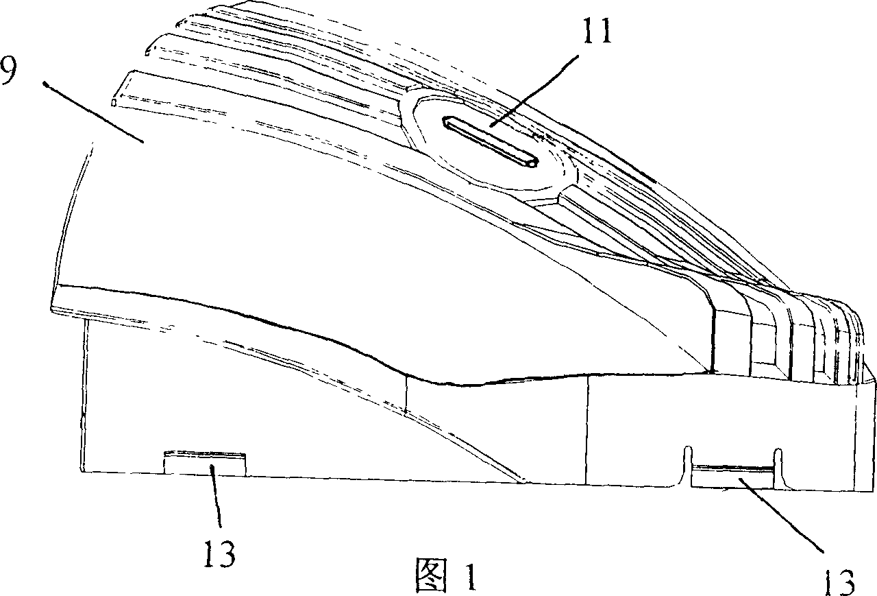
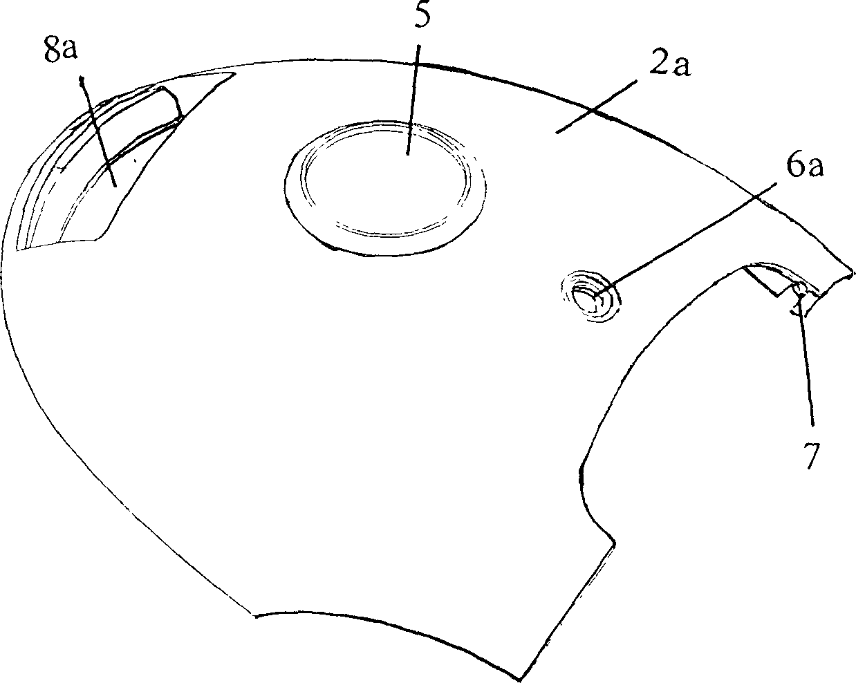
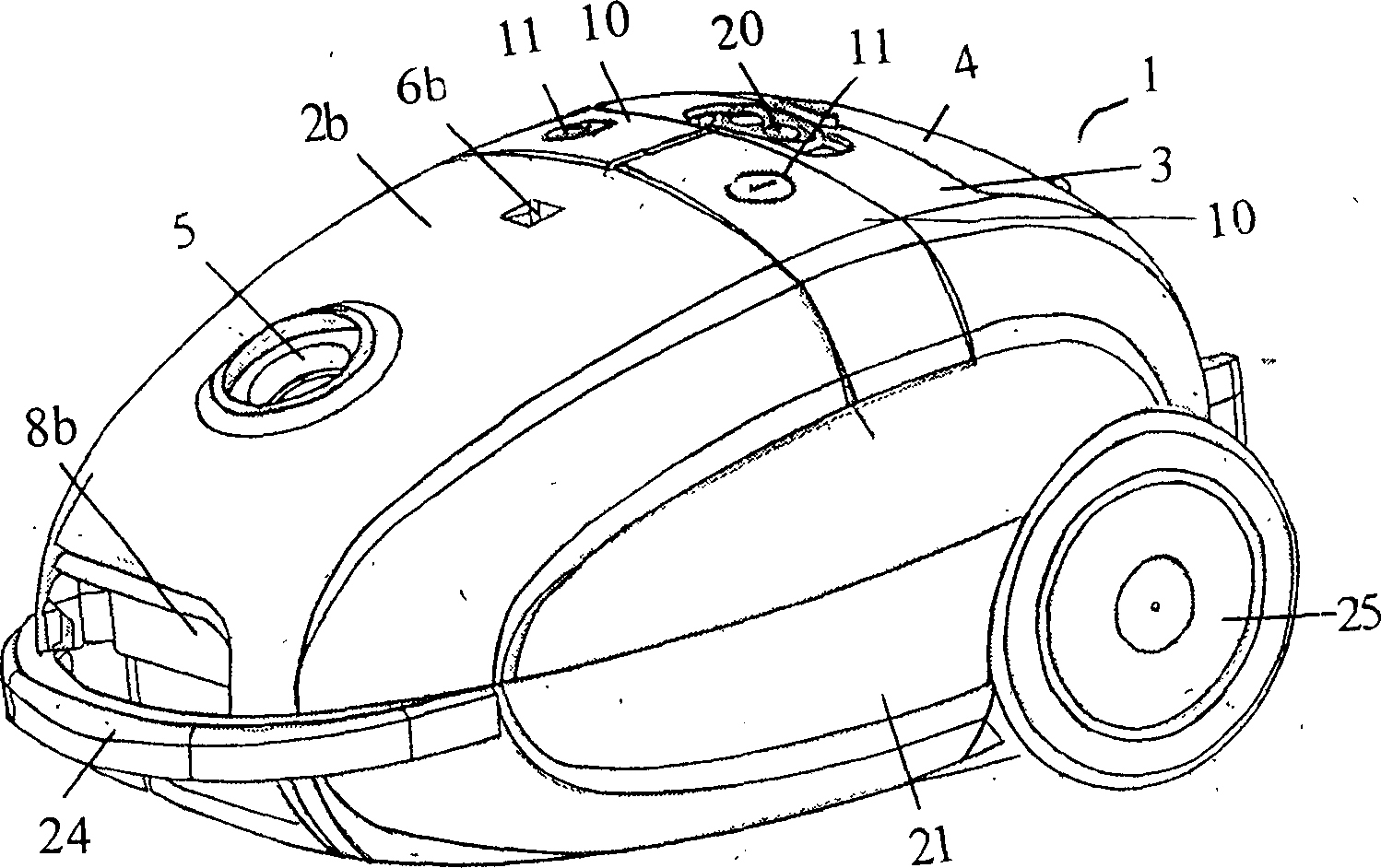
[0036] A key protection structure of a vacuum cleaner includes a front cover 2b provided with a hose interface 5, a display window 6b and a flip groove 8b and covering the front of the bottom shell 21 to form a dust box 12, and the dust box 12 is provided There is a dust bag holder 23; between the front cover 2b and the rear cover 4, a button 10 that covers the front power switch contact and the reel switch contact of the cover simplified 3 is installed; and the outer end of the cover of the button 10 is connected to the simplified 3 The side walls are hinged, the button front wall 16 has an action limit gap 14 in the middle, the folding arm 18 at the rear end of the front cover 2b extends into the action limit gap 14 and is connected with the front hinge of the simplified 3, the folding arm 18 is ...


PUM


Abstract

A push button protecting structure for cleaner is composed of a front cover to form a dust collecting box, the bush buttons arranged between front cover and back cover for covering on the contacts of power switch and power cord winder and with an operation limiting notch at the middle of its front wall, and a curved arm able to be inserted in said limiting notch. Its advantages are short stroke, the ability to lock the push button, and beautiful appearance.

Description

technical field [0001] The invention relates to an electrical mechanical device of a vacuum cleaner, in particular to a key protection structure of the vacuum cleaner. Background technique [0002] Vacuum suction is a cleaning and sanitary appliance used to remove dust from floors, carpets, walls, furniture, clothing and various gaps. [0003] A vacuum cleaner generally consists of a vacuum cleaner motor that generates suction from an imported power supply, a suction nozzle, a hose, a filter bag forming an air path system, and a dust collection part that collects inhaled matter. [0004] According to the shape of vacuum cleaners, they can be divided into upright vacuum cleaners, horizontal vacuum cleaners and portable vacuum cleaners. [0005] The body of the upright vacuum cleaner generally includes a front cover 2 a , a body 3 , a rear cover 4 and a bottom case 21 . The front end of the front cover 2a is a flip cover groove 8a, the top is provided with a hose interface 5...

Claims


Application Information

Patent Timeline
IPC IPC(8): A47L5/00A47L9/00
Inventor 辛继哲
Owner LG ELECTRONICS (TIANJIN) APPLIANCES CO LTD
Why Eureka
Try Eureka