

Piston rod mechanism with guide slot in curved face on surface of rotator
A technology of rotating body and piston rod, applied in the field of piston rod mechanism, can solve the problems of reduced mechanical efficiency, damaged piston and cylinder wall, reduced output torque, etc., to meet technical requirements, improve work efficiency, and meet the effect of high-speed rotation
- Summary
- Abstract
- Description
- Claims
- Application Information
AI Technical Summary
Problems solved by technology
Method used
Image

Examples
Embodiment 1
[0030] In this embodiment, on the basis of Chinese patent 85102435.1, the curve of the guide groove on the surface of the rotating body is optimally designed to meet the technical requirements for the rotating body to rotate at a high speed.
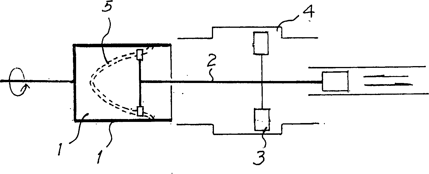
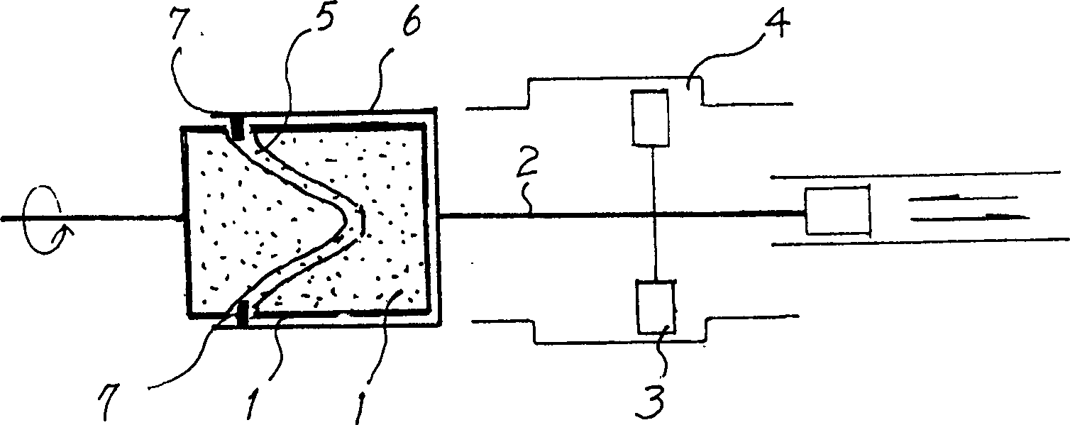
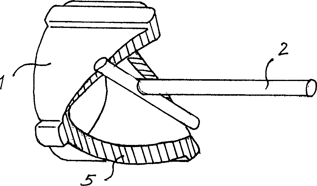
[0031] The cylinder piston rod 2 uses a "T" shaped rod, and the "T" shaped head is connected to the rotating body. The middle section of the "T" shaped main rod is provided with a slider 3, and the sliding block 3 is in the chute 4; The inner surface of the garden tube is provided with a curved guide groove 5; the head of the "T" shaped rod is connected to the rotating body in such a way that the two ends of the "T" shaped head are respectively inserted into the curved surface guide groove 5, so that " The T"-shaped head can only slide in the curved surface guide groove 5; the slider 3 has a flat surface, and the chute 4 is matched with the slider 3, so that the slider 3 can only reciprocate in the chute 4, thereby limiting the "T" "The ...
Embodiment 2
[0038] In this embodiment, on the basis of Chinese patent 85102435.1, the curve of the guide groove on the surface of the rotating body is optimally designed to meet the technical requirements for the rotating body to rotate at a high speed.
[0039] The cylinder piston rod 2 uses a "T"-shaped rod, and the "T"-shaped head matches the curved surface guide groove 5 in the rotating body. Coordination; the rotating body 1 is a garden pipe, and a curved surface guide groove 5 is provided on the inner surface of the garden pipe; the head of the "T" shaped rod is connected to the rotating body by inserting the two ends of the "T" shaped head into the curved surface respectively In the guide groove 5, the "T"-shaped head can only slide in the curved surface guide groove 5; the slider 3 is a square, and the chute 4 is a shape that matches the slider 3, so that the slider 3 can only be used in the chute 4. Reciprocating movement, thereby restricting the rotation of the "T" shaped rod, s...
Embodiment 3
[0046] In this embodiment, on the basis of Chinese patent 85102435.1, the curve of the guide groove on the surface of the rotating body is optimally designed to meet the technical requirements for the rotating body to rotate at a high speed.
[0047] The cylinder piston rod 2 uses a "T" shaped rod, and the "T" shaped head is connected to the rotating body. The middle section of the "T" shaped main rod is provided with a slider 3, and the sliding block 3 is in the chute 4; The inner surface of the garden tube is provided with a curved guide groove 5; the head of the "T" shaped rod is connected to the rotating body in such a way that the two ends of the "T" shaped head are respectively inserted into the curved surface guide groove 5, so that " The T"-shaped head can only slide in the curved surface guide groove 5; the slider 3 is made of a square, and the chute 4 is in a shape that matches the slider 3, so that the slider 3 can only reciprocate in the chute 4, thereby limiting th...
PUM
 Abstract
Description
Claims
Application Information