Glass bulb for cathode ray tube

A cathode ray and tube technology, applied in the direction of cathode ray/electron beam tube shell/container, cathode ray tube/electron beam tube, discharge tube, etc., can solve the problem of increasing the overall depth of the main body, and avoid concentration and suppression Increase in mass, effect of suppressing stress

Inactive Publication Date: 2006-07-05
ASAHI GLASS CO LTD
View PDF3 Cites 0 Cited by
  • Summary
  • Abstract
  • Description
  • Claims
  • Application Information

AI Technical Summary

Problems solved by technology

use Figure 7 In the case of the shape, the overall depth of the main body increases, and there are problems in design

Method used


Image

  • Glass bulb for cathode ray tube
  • Glass bulb for cathode ray tube
  • Glass bulb for cathode ray tube

Examples


Embodiment 1

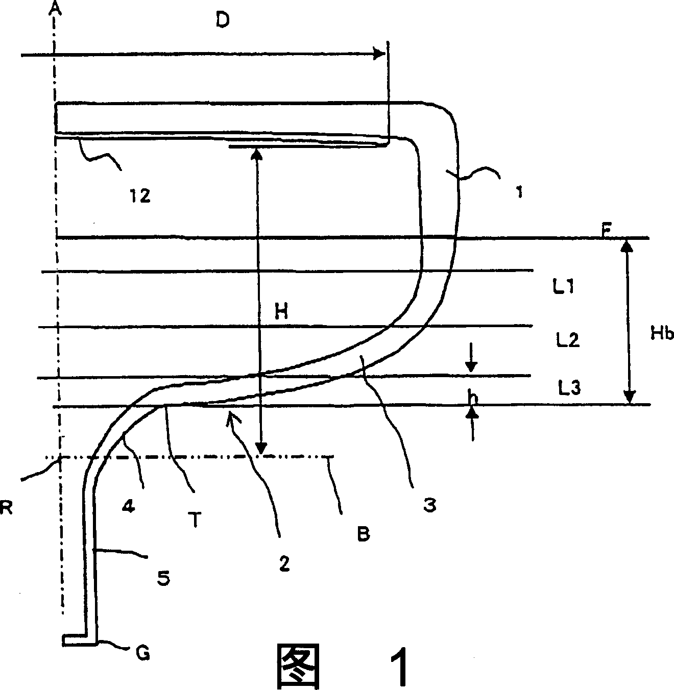
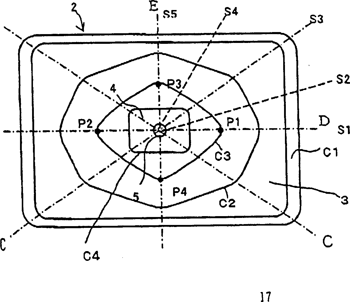
[0076] 0.1H of the main body with a maximum effective screen diameter of 676mm b b The cross-sectional external shape of the region (hereinafter referred to as the position of the present invention) is figure 2 In the rhomboid-like embodiment shown, the stress of each part is within the standard, and the quality can be designed to be the lightest.

Embodiment 2

[0078] By changing the shape of the approximately rhombic section in Embodiment 1, the stress of the deflection yoke portion can be designed to be lower.

Embodiment 3

[0080] The maximum diameter of the effective screen is 760mm, and the cross-sectional external shape of the part of the present invention is figure 2 In the example shown in the approximate rhombic shape, the stress of the deflection yoke portion of Comparative Example 4 which does not have the structure of the present invention can be lowered by 1.4 MPa, which satisfies the standard of stress. The mass can be designed to be approximately the same as Comparative Example 4.


PUM


Abstract

To provide a glass bulb for a flat cathode-ray tube small in weight and excellent in productivity. In this highly reliable flat cathode-ray tube, the outline thereof near a yoke part in a cross section vertical to the tube axis of a body part 3 is formed in an approximately rhombus shape or an approximately bobbin shape. The direction of the maximum diameter of the approximately rhombus shape in cross section is aligned with the direction of the major axis of a funnel. When the outline is formed in the approximately bobbin shape, its maximum diameter part is disposed between the major axis and a diagonal axis. Where a distance from the maximum diameter part to a yoke end is (s) in the vertical direction to the tube axis, the minimum value of the differential value of H = f (s) is set to 0 or higher, and the body part is formed of a smooth continuous surface without step parts, projections, or dents to reduce a stress generated in a yoke portion.

Description

technical field [0001] The present invention relates to a vacuum glass envelope for a cathode ray tube mainly used for television signal reception and industrial terminal equipment. Background technique [0002] In cathode ray tubes, such as Image 6 As shown, the vacuum bulb basically composed of a glass screen 1 and a funnel 2 for displaying images constitutes a vacuum bulb. Furthermore, the funnel 2 is composed of a neck portion 5 on which the electron gun is placed, a deflection yoke portion 4 on which a deflection yoke is installed, and a main body portion 3 formed from the deflection yoke portion to the sealing portion with the panel. Image 6 Among them, 16 is a reinforcing belt for maintaining strength against impact, 10 is a sealing part that seals the glass panel 3 and the funnel 2 with solder glass, etc., 12 is a fluorescent film that emits fluorescence when irradiated by electron beams, and 13 is The aluminum film that the light that fluorescent film sends is ref...

Claims


Application Information

Patent Timeline
Patent Type & Authority Applications(China)
IPC IPC(8): H01J29/86
CPCH01J2229/8606H01J29/861H01J29/86
Inventor 村上敏英
Owner ASAHI GLASS CO LTD
Why Eureka
Try Eureka