Method of using buffer area

A technology of buffer area and sub-cache, applied in the computer field, can solve the problems of reducing the number of buffer areas, insufficient buffer area, suspending work, etc., to achieve the effect of improving the utilization rate

Inactive Publication Date: 2006-07-05
HUAWEI TECH CO LTD
0 Cites 34 Cited by

AI-Extracted Technical Summary

Problems solved by technology

[0008] But this method of using the cache will lead to new problems: allocating a cache for each connection will greatly increase the demand for the cache, and cause some caches corresponding to connections with low traffic to always be idle; or when When the number of buffers is constant, th...

Abstract

The method includes following steps: the buffer pool is divided into the private sub buffer pool and the shared buffer pool; then sets up a coincidence relation between the private buffer pool and the channel carrying data; applies buffer area to the private buffer pool in term of the coincidence relation; when the data flow exceeds the capacity of the private buffer pool, applies the buffer area to the shared buffer pool.

Application Domain

Technology Topic

Traffic volumeCoincidence +1

Image

  • Method of using buffer area
  • Method of using buffer area
  • Method of using buffer area

Examples

  • Experimental program(3)

Example

[0056] The first embodiment: AAL5 is a connection-oriented service. When data transmission is required, a permanent virtual circuit (PVC) (Permanent Virtual Circuit) between the sending end and the receiving end is first established, and the data is transmitted through the permanent virtual circuit.
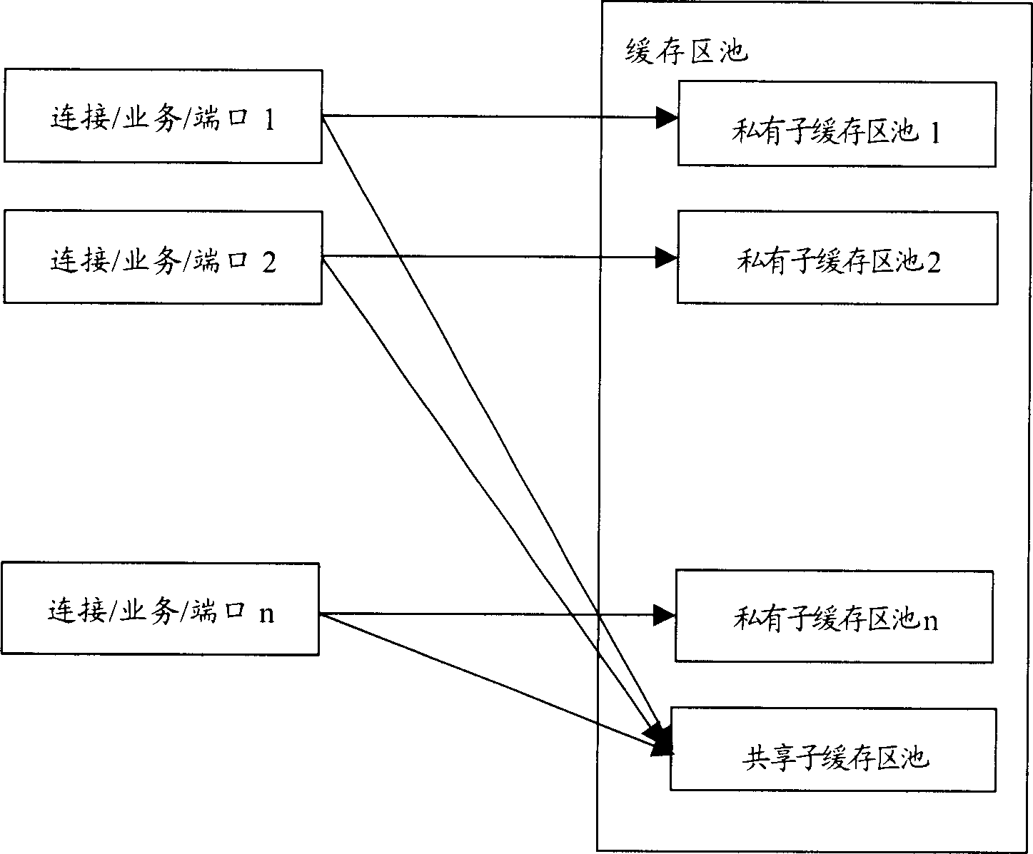
[0057] When the present invention is applied to AAL5 data transmission, the buffer pool is first divided into a predetermined number of private sub-buffer pools and shared sub-buffer pools; due to the connection-based data transmission method, both ends of the channel have the same network Identification (VPI (Virtual Pass Identifier, virtual path identifier), VCI (Virtual Channel Identifier, virtual channel identifier)). Therefore, the corresponding relationship between the data transmission channel and the private sub-buffer pool can be set according to the network identifier.
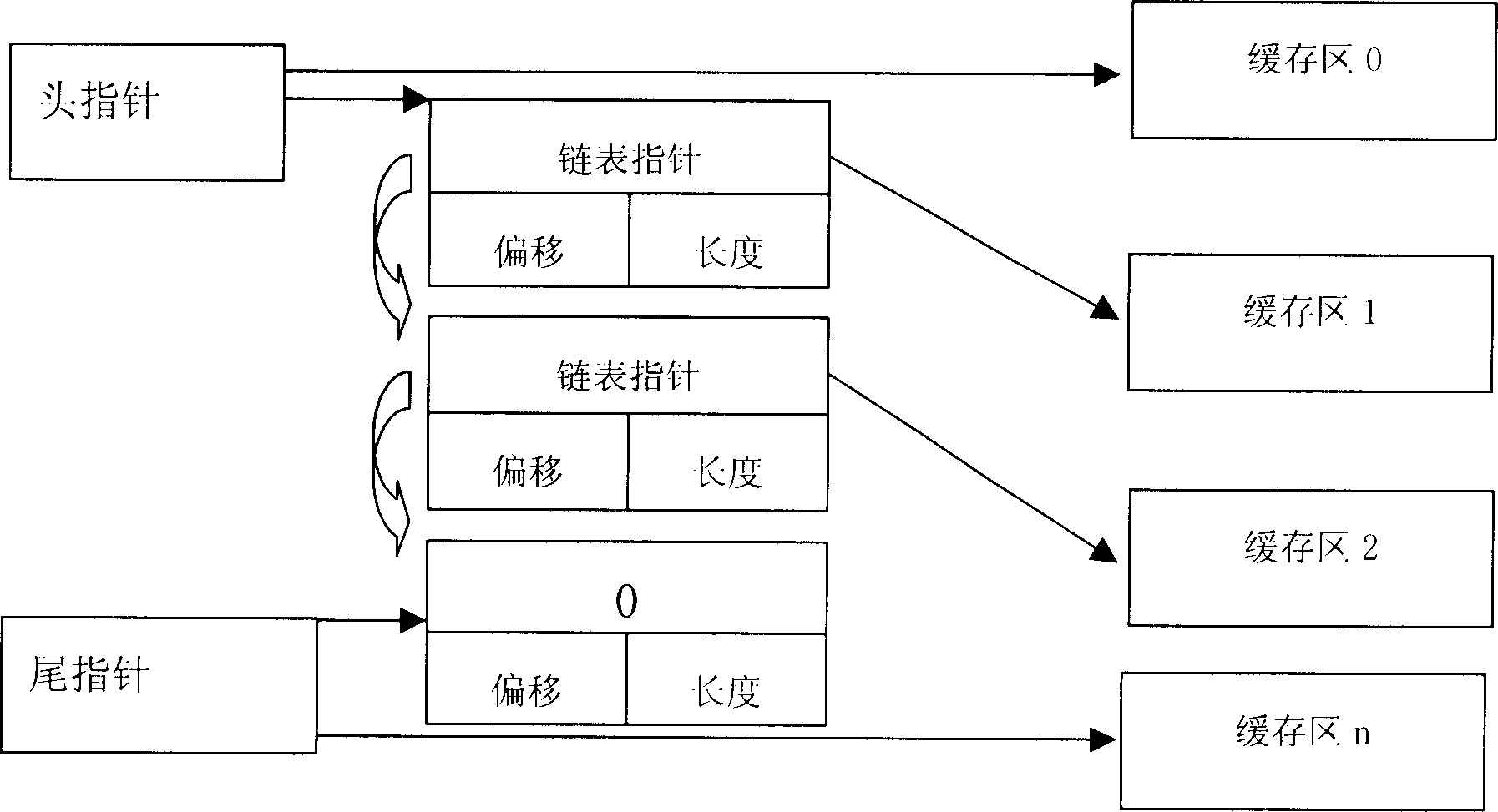
[0058] The method of using each private sub-buffer pool is the same as the method of dynamically using the buffer in the prior art. In order to facilitate the understanding of the process of applying for a buffer in the present invention, first review the related well-known principles in the prior art.
[0059] For the method of dynamically using the buffer area, a dynamic linked list is usually used. image 3 It is a structural intention of dynamic management.
[0060] As shown in the figure, firstly, each private sub-buffer pool is divided into N buffers, and each buffer is identified by a buffer descriptor. The information data contained in each buffer descriptor includes: linked list pointer (The next buffer descriptor address NextBufHandle), displacement, length and other information. The system implements the management of each buffer descriptor through pointers. A buffer descriptor uniquely points to a buffer address, and the system maintains two pointers: head pointer and tail pointer, which point to the head and tail of the linked list respectively. The NextBufHandle field value of the buffer descriptor initially pointed to by the tail pointer is 0.
[0061] Buffer application: When a connection needs to apply for a buffer area, first find the corresponding private sub-buffer pool according to the network identifier of the channel, and then check whether the sub-buffer pool has available buffer resources, and if it exists, it will be idle The buffer area is allocated to the connection. The specific process is: if the head pointer and the tail pointer overlap, it means that the sub-buffer pool has no available buffer area; otherwise, the buffer area corresponding to the buffer area descriptor pointed to by the head pointer head of the linked list is taken out, and the head pointer is at the same time Point to the buffer descriptor pointed to by the NextBufHandle field in the buffer descriptor of the private sub-buffer pool;
[0062] Buffer release: When the buffer area needs to be released after using it, first change the NextBufHandle field of the buffer area descriptor pointed to by the Tail pointer to the buffer area descriptor address of the current buffer area, and then the tail pointer points to the currently released buffer area Buffer the descriptor address, and change the NextBufHandle of the descriptor to 0.
[0063] When the head pointer coincides with the tail pointer, it means that there is no free buffer area behind the entire private sub-buffer area pool. At this time, check whether there is a free buffer area in the shared sub-buffer area pool. The method of using the shared sub-buffer pool is the same as the method of the above-mentioned private sub-buffer pool, and the method of checking whether there is a free buffer is also the same as described above, and will not be repeated here.
[0064] If there is a free buffer area in the shared sub-buffer area pool, the free buffer area is allocated to the connection of the buffer area application for the buffer area; when the shared sub-buffer area pool has been occupied, the buffer area application failure processing is performed.

Example

[0065] The second embodiment: SSCOP (Service Specifical Conection Orientated Protocol, connection-oriented protocol for specific services) IPOA (IP Over ATM) is a different upper-layer service based on AAL5 connections, and the protocol groups are SSCOP/AAL5/ATM, IPOA/AAL5/ATM. .
[0066] In order to prevent different services from affecting each other, it is usually necessary to allocate different buffer areas for different types of services. When the present invention is applied to these two services, the buffer pool is first divided into two private sub-buffer pools and one shared sub-buffer pool for the two business types; then the private sub-buffer pools are allocated to For the channel corresponding to each service, for example, pool 1 is allocated to SSCOP, pool 2 is allocated to IPOA, and pool 3 is a shared buffer.
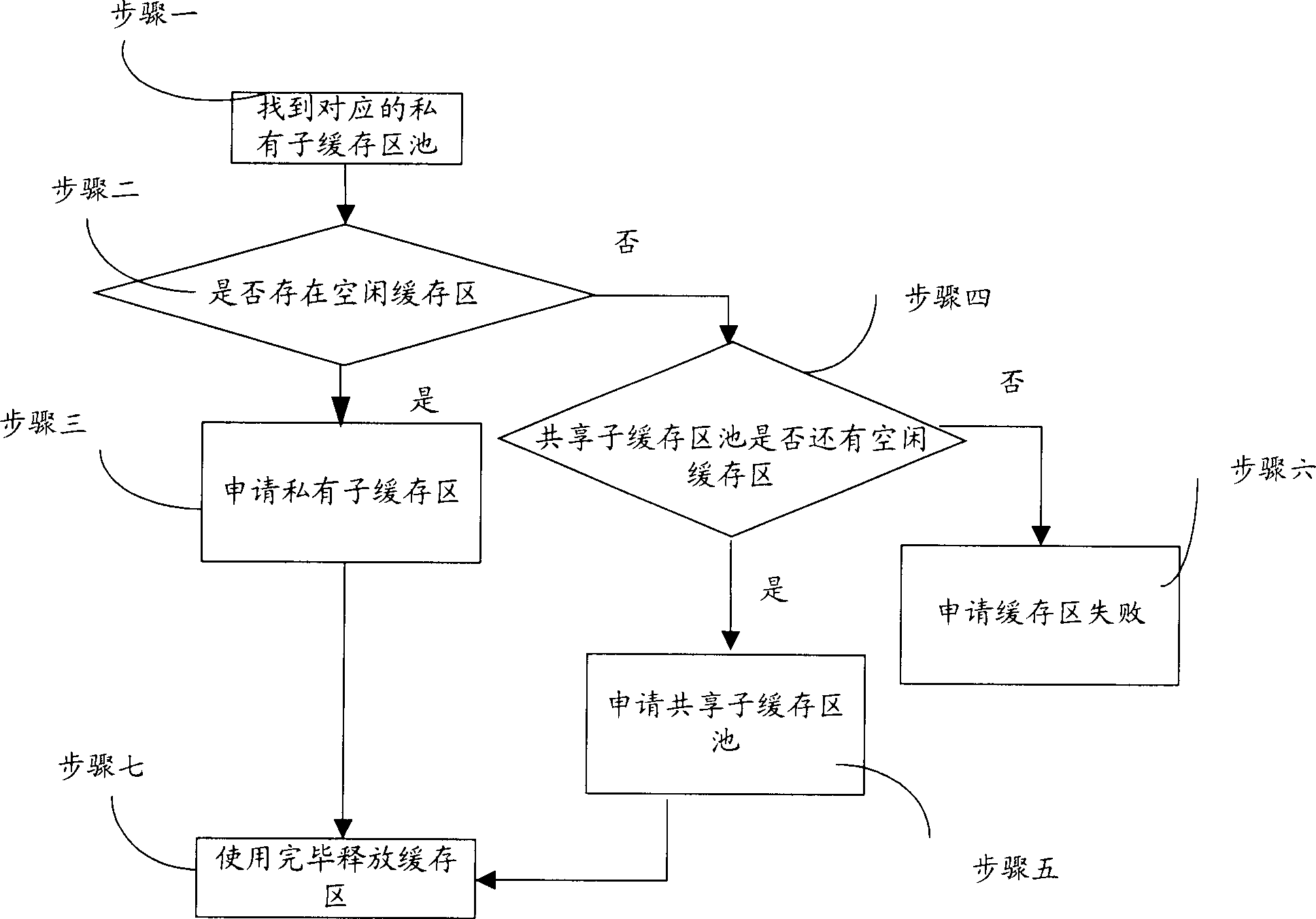
[0067] When data transmission is required, first find the corresponding private sub-buffer pool according to the service type of the PVC, and then check whether the private sub-buffer pool has a buffer in an idle state. The checking method is the same as that described in the first embodiment. I won't repeat them here.
[0068] When there is a free buffer area, it is allocated to the service channel applying for the buffer area; otherwise, it is checked whether there is a buffer area available for use in the shared sub-buffer area pool. When there is a buffer area available for use, it is allocated to the service channel applying for the buffer area. When no available buffer area is found in the shared sub-buffer pool, application failure processing is performed.

Example

[0069] The third embodiment: In a communication system, there are different trunk lines between different network nodes. In order to ensure that data from different ports does not interfere with each other, it is necessary to allocate different buffer areas for data from different physical ports during transmission. . When the present invention is applied, different private sub-buffer pools are allocated for data from different physical ports, and a buffer area is allocated as a shared buffer for each physical port. The current port types include trunk mapping ports, connection ports between circuit boards, and optical/electrical interfaces. Therefore, the correspondence between the data transmission channel and the private sub-buffer pool can be set according to the port type. The specific management method of the buffer is consistent with the previous example.
[0070] When data transmission needs to be performed, first find the corresponding private sub-buffer pool according to the port type, and then check whether there is an idle buffer in the private sub-buffer pool. The checking method is the same as the foregoing embodiment, and will not be repeated here.
[0071] The above three embodiments describe the specific process of allocating buffer areas for data transmitted in three ways. When the transmitted data contains data combined in several ways, the present invention is also applicable. At this time, when establishing the corresponding relationship between the channel and the sub-buffer pool, you only need to establish the corresponding relationship between the various types of channels and the sub-buffer pool according to the above method. The specific application method is as described above and will not be repeated. .

PUM

no PUM

Description & Claims & Application Information

We can also present the details of the Description, Claims and Application information to help users get a comprehensive understanding of the technical details of the patent, such as background art, summary of invention, brief description of drawings, description of embodiments, and other original content. On the other hand, users can also determine the specific scope of protection of the technology through the list of claims; as well as understand the changes in the life cycle of the technology with the presentation of the patent timeline. Login to view more.

Similar technology patents

Method for preparing polypeptide fruit jelly

InactiveCN1864528AEasy to carryIncrease usageVegetable proteins working-upNutrientBoiling point
Owner:CHINA RES INST OF DAILY CHEM IND

Floating leisure platform

InactiveUS20060162637A1Increase usageIncrease attractivenessLife-buoysRaftsMarine engineeringIngested food
Owner:ZEUS

Classification and recommendation of technical efficacy words

Why Eureka
Try Eureka