
Electric motor

A technology of electric motor and electric angle, applied in the field of electric motor

Inactive Publication Date: 2006-07-05
HITACHI LTD +1
View PDF4 Cites 17 Cited by
  • Summary
  • Abstract
  • Description
  • Claims
  • Application Information

AI Technical Summary

Problems solved by technology

However, it does not necessarily have a suppression effect on the axial bending deformation mode of the stator caused by the electromagnetic exciting force in the radial direction of the inner type motor.

Method used


Image

  • Electric motor
  • Electric motor
  • Electric motor

Examples


Embodiment Construction

[0048] Hereinafter, embodiments of the present invention will be described with reference to the drawings.

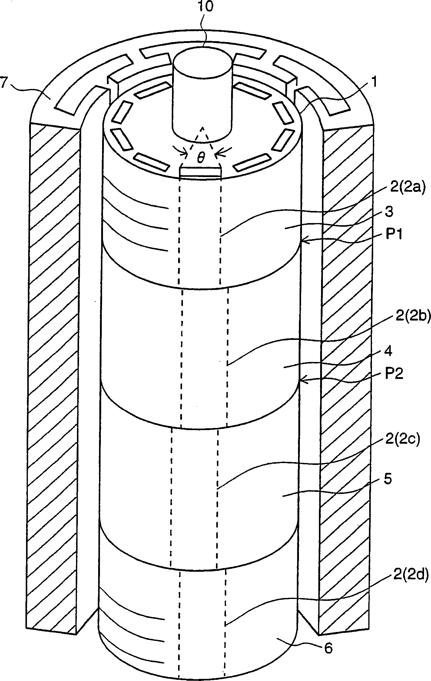
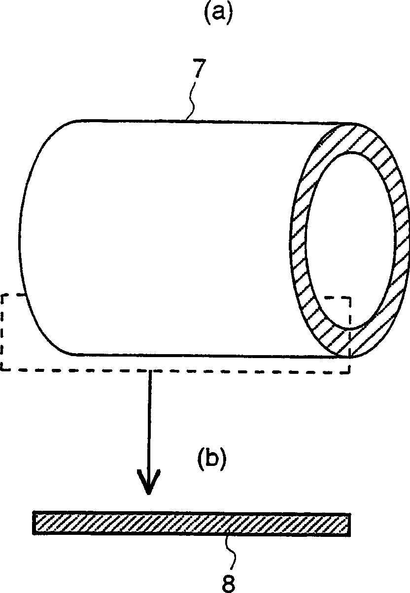
[0049] figure 1 It is a figure which shows an Example of the rotor 1 and the stator 7 when the permanent magnet motor of the electric motor 100 of this invention was taken as an example. image 3 A conceptual diagram showing a stator core (stator) 7, image 3 (a) represents a cylindrical graph, image 3(b) shows its section. In these figures, the magnetic core of the rotor 1 is formed by stacking laminated steel plates, and the stacked steel plates are divided into a plurality of blocks in the axial direction, that is, divided into rotor blocks. figure 1 The middle rotor 1 is composed of four rotor blocks 3, 4, 5, 6, a shaft 10 and permanent magnets 2 (2a, 2b, 2c, 2d) having the same length in the axial direction of the rotor blocks 3, 4, 5, 6 . Each permanent magnet 2 has an effective pole opening angle θ.

[0050] figure 1 In , the permanent magnet 2 constituti...


PUM


Abstract

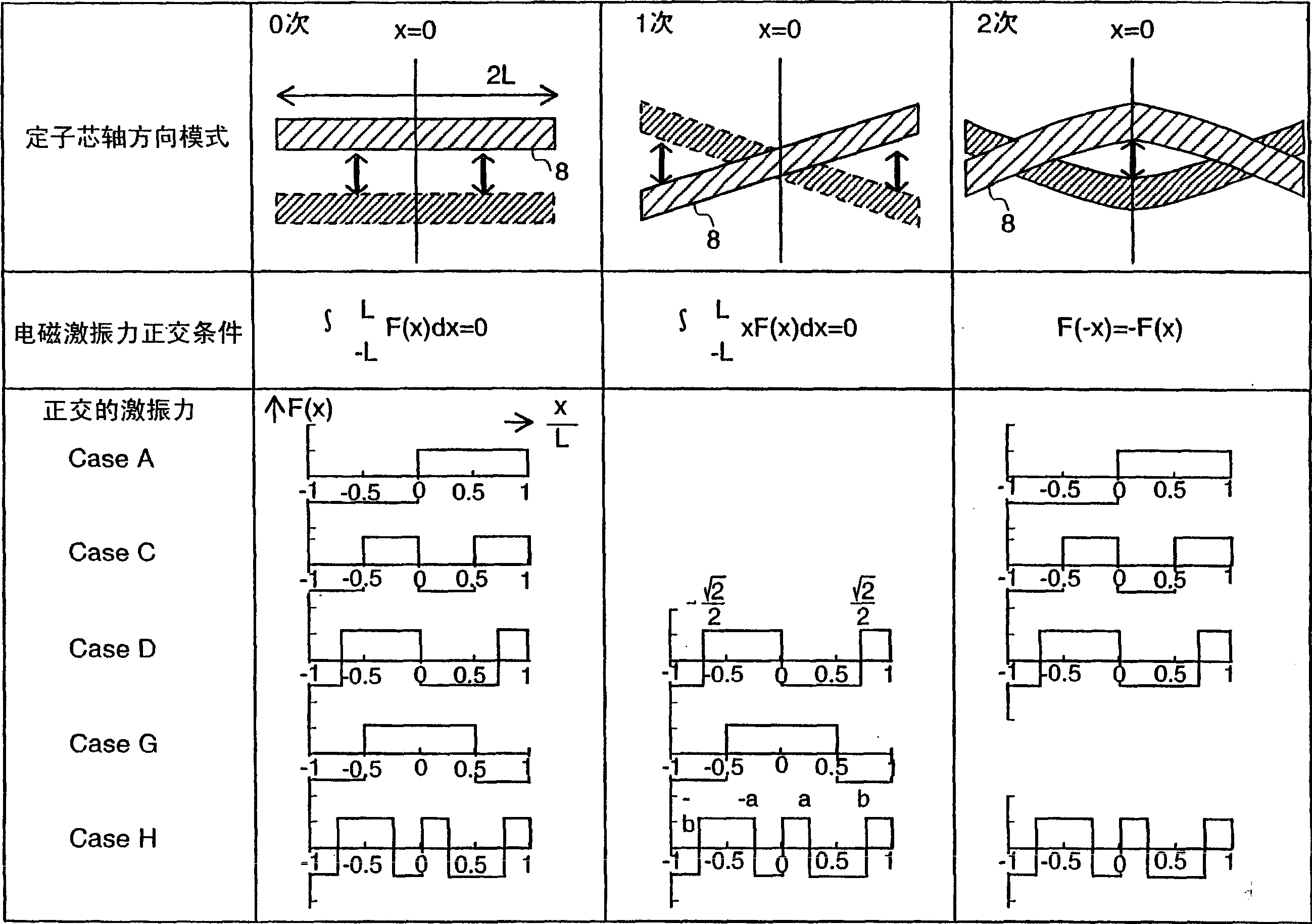
It is possible to suppress vibration and noise caused by radial-direction electromagnetic excitation force of an electric motor. In an electric motor (100), a rotor (1) is divided into four rotator pieces (3, 4, 5, 6) with respect to a shaft length 2L of a group of rotor cores. For example, it is ideal that the four rotor pieces (3, 4, 5, 6) respectively have a shaft-direction length: 0.29L, 0.71L, 0.71L, and 0.29L. Permanent magnets (2) of the respective rotor pieces (3, 4, 5, 6) are arranged in such a manner that the phase difference of the electrical angle in the circumferential direction of the rotor (1) is 0, pi, 0, pi. Moreover, when effect can be obtained even when the theoretical shaft length is changed, the tolerance with respect to the aforementioned shaft length is +-0.1L.

Description

technical field [0001] The present invention relates to a motor, in particular to a structure for suppressing electromagnetic oscillation and noise caused by the electromagnetic exciting force in the radial direction of the variable frequency speed regulating motor. Background technique [0002] Electric motors are often used in home appliances and various OA devices, and in recent years are mounted in electric vehicles. [0003] These motors are required to be large for their output, and thus generate oscillation and noise caused by electromagnetic exciting force. [0004] The electromagnetic exciting force in the radial direction is generated when the rotor and the stator move relatively. The magnetic circuit of the magnetic flux generated by the magnetic poles of the rotor changes periodically every time the magnetic poles of the rotor cross the opening of the slot provided on the stator, thereby causing resulting from changes in the magnetic flux distribution across the...

Claims


Application Information

Patent Timeline
Patent Type & Authority Applications(China)
IPC IPC(8): H02K1/18H02K1/27H02K21/14H02K29/03
CPCH02K2201/06H02K29/03H02K1/165H02K1/187H02K1/27
Inventor 根本佳奈子高野靖高木亨之田岛文男根津章山崎司大木俊治木村真秀藤田育志
Owner HITACHI LTD
Learn More