Image receiving apparatus and image reproducing apparatus

An image receiving and reproducing device technology, applied in image communication, television, simultaneous/sequential multi-television signal transmission, etc., can solve the problems such as the recording method cannot be reproduced, the processing method is different, and the display form cannot be correctly converted.

Inactive Publication Date: 2006-07-05
SHARP KK
View PDF1 Cites 35 Cited by
  • Summary
  • Abstract
  • Description
  • Claims
  • Application Information

AI Technical Summary

Problems solved by technology

However, if the data format of the image to be reproduced is different, the required processing methods are also different, so even in the same reproduction device, if the data format of the image to be reproduced is unknown, it cannot be converted to the display format correctly.
On the contrary, even if the images taken by the same camera are displayed in different ways on the playback device side, the required processing methods are different, so they cannot be converted correctly.
[0013] That is, although it is sufficient to have a one-to-one correspondence between the shooting device and the reproducing device, since the shooting conditions and the reproducing conditions need to be consistent in order to exchange images between different devices, the commonality of the captured image will be greatly damaged. The problem
[0014] Moreover, although identification information is recorded not only in stereoscopic photography but also in monocular photography, there is a problem that it cannot be reproduced in other devices due to the recording method.

Method used


Image

  • Image receiving apparatus and image reproducing apparatus
  • Image receiving apparatus and image reproducing apparatus
  • Image receiving apparatus and image reproducing apparatus

Examples


no. 1 Embodiment approach

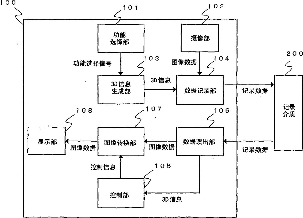
[0045] FIG. 1 is a block diagram showing the configuration of an image recording device 100 according to a first embodiment of the present invention.

[0046] Referring to FIG. 1 , an image recording device 100 records an image of a subject on a recording medium 200 and reproduces the image recorded on the recording medium 200 . Therefore, the image recording device 100 also functions as an image reproduction device.

[0047] The image recording device 100 is provided with: a function selection unit 101 for selectively switching the photography function of monocular photography and stereoscopic photography; an imaging unit 102 equipped with an imaging element such as a CCD (Charge Coupled Device, charge coupled device) or an autofocus circuit; The 3D information generating unit 103 generates 3D information in a predetermined format (hereinafter referred to as “3D information”); and the data recording unit 104 formats image data and 3D information and records them on the record...

no. 2 Embodiment approach

[0079] Fig. 7 is a kind of image reproducing system, it connects the image sending device 140 that sends image data and the image receiving device 150 that receives image data through channel 160, exchanges order through channel 160, and this order is used for other image data The connected device is controlled.

[0080] FIG. 8 is a block diagram showing a configuration example of the image transmission device 140 .

[0081] In FIG. 8 , the same parts as in FIG. 1 are given the same symbols, and the description thereof will not be repeated. The image transmission device 140 includes a function selection unit 101, an imaging unit 102, a 3D information generation unit 103, a data recording unit 141, a control unit 105, a data readout unit 142, an image conversion unit 107, a display unit 108, a sending unit 143, a receiving unit part 145 and recording medium 200.

[0082] The operation of the image transmission device 140 configured as above will be described below. However, ...

no. 3 Embodiment approach

[0129] Next, in the image receiving device 150 shown in FIG. 11 , a method of creating a list of image contents recorded in the recording medium 200 mounted in the image transmitting device 140 and presenting the list to the user will be described.

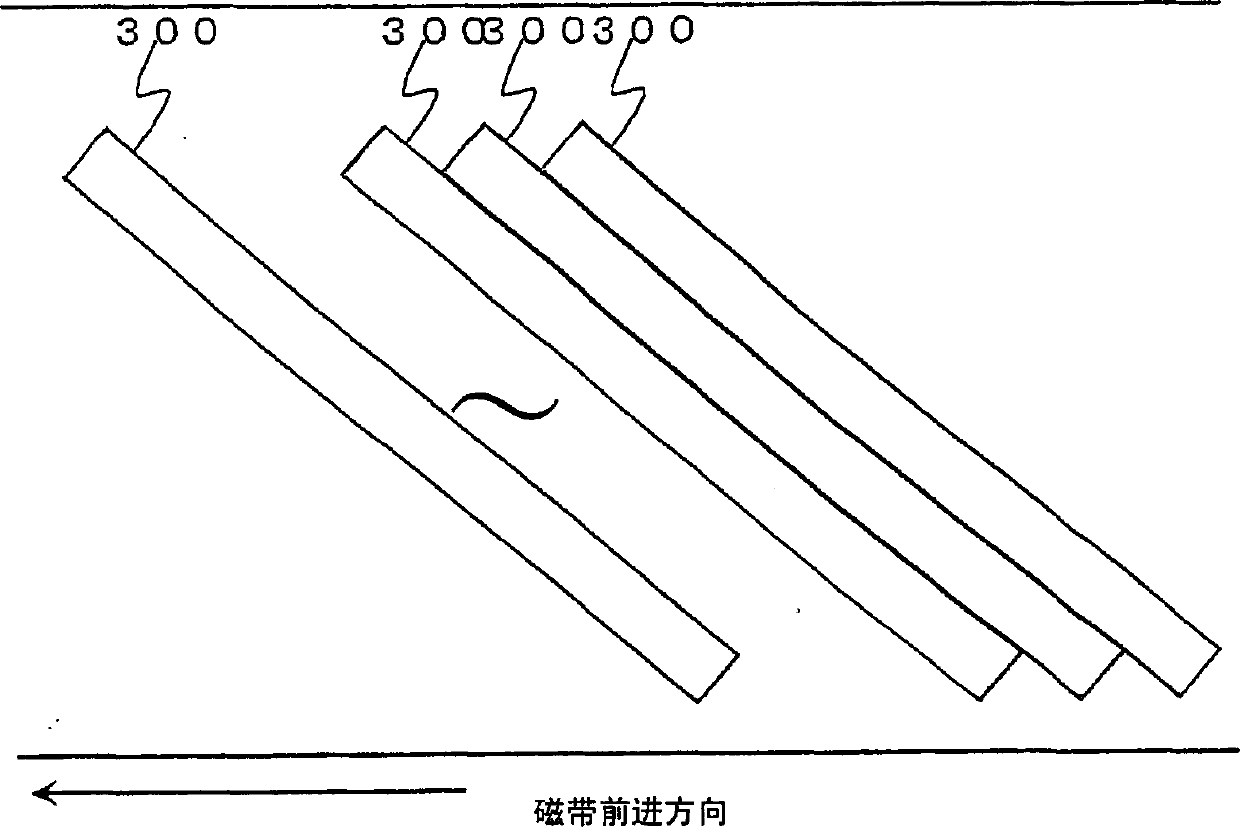
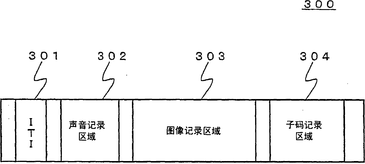
[0130] Here, the case where the DV method is used as the recording method is taken as an example as described above. And, when recording the image data in the recording medium 200, as shown in FIG. When the medium performs a high-speed search, only the subcodes in the data read from the recording medium 200 are packaged and sent to the channel 160 .

[0131] The image receiving device 150 receives the data packet from the channel 160, and sets the first received time code as the start position of the first image content. If the data packet contains 3D information, then let the attribute be 3D, otherwise it is 2D. Next, when the presence or absence of 3D information changes, that is, when the above-mentioned attribute is 3D, when...


PUM


Abstract

The present invention relates to a video receiving apparatus receiving, from a communication channel, video data of three-dimensional video taken using binocular parallax and added information for the video data, or to a video reproducing apparatus reading such from a recording medium. The video receiving apparatus or video reproducing apparatus detects added information indicating a predetermined format for three-dimensionally displaying the video data, and three-dimensionally displays video data that conforms to the predetermined format. The video receiving apparatus uses a data reception unit (151) to receive multiplexed data including video data and added information and uses a data separation unit (152) to extract the video data and its added information. A control unit (153) controls a video conversion unit (155) based on the added information to convert the video data to three-dimensional video that conforms to the predetermined format and display it on a display unit (156).

Description

technical field [0001] The present invention relates to an image receiving device for capturing a 3-dimensional image using binocular parallax and receiving image data transmitted through a channel for 3-dimensional display, and for capturing a 3-dimensional image using binocular parallax and An image reproduction device that reads image data recorded on a recording medium and displays it in 3D. Background technique [0002] Conventionally, as a method for photographing a stereoscopic image in which the photographed subject can be viewed stereoscopically by seeing a plurality of images with parallax with the left and right eyes respectively, it means A single-lens camera is equipped with a stereo adapter that forms a plurality of subject images with different viewpoints, and a plurality of images with parallax in one screen are captured. [0003] 20A to 20C are diagrams for explaining captured images when the stereoscopic image adapter is attached. [0004] Fig. 20A is the...

Claims


Application Information

Patent Timeline
Patent Type & Authority Applications(China)
IPC IPC(8): H04N13/04H04N5/91H04N7/08H04N7/081H04N13/00
CPCH04N13/0454H04N13/0456H04N13/0289H04N13/0048H04N13/0066H04N13/0059H04N13/0055H04N9/8227H04N13/004H04N19/00769H04N19/597H04N13/289H04N13/194H04N13/189H04N13/156H04N13/161H04N13/359H04N13/361H04N13/178H04N13/00
Inventor 伊藤元浩大原一人
Owner SHARP KK
Why Eureka
Try Eureka