Coded video sequence conversion apparatus, method and program product for coded video sequence conversion

A technology for encoding video sequences and transforming devices, which is applied in the fields of digital video signal modification, television, and pulse modulated television signal transmission, and can solve problems such as the inability to perform effective transformation of encoding parameters and the inability to effectively set macroblock encoding parameters.

Inactive Publication Date: 2006-07-12
KK TOSHIBA
View PDF1 Cites 4 Cited by
  • Summary
  • Abstract
  • Description
  • Claims
  • Application Information

AI Technical Summary

Problems solved by technology

Thus, several constraints arise so that the upper macroblock and the lower macroblock included in each macroblock pair match on the encoding structure, and make it necessary to separately manage the top field (top field) for the upper macroblock and the lower macroblock. ) and the encoding parameters of the bottom field
[0007] Therefore, in order to transform an interlaced input signal from a video coded video sequence encoded with MPEG-2 compression to a video coded video sequence in an H.264 coding format, in the related art, macroblock coding parameters are set for each macroblock, And therefore it is impossible to efficiently set the encoding parameters of the macroblock pair while satisfying the constraints on the macroblock pair
[0008] As mentioned above, in conventional transcoding systems, efficient transformation from the coding parameters of macroblocks in the first video-coded video sequence to the coding parameters of macroblock pairs in the second video-coded video sequence cannot be performed

Method used


Image

  • Coded video sequence conversion apparatus, method and program product for coded video sequence conversion
  • Coded video sequence conversion apparatus, method and program product for coded video sequence conversion
  • Coded video sequence conversion apparatus, method and program product for coded video sequence conversion

Examples


no. 1 example

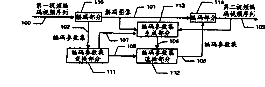
[0036] Fig. 1 is a block diagram showing a video coding video sequence conversion apparatus according to a first embodiment.

[0037] The video coding video sequence conversion device according to the first embodiment includes:

[0038] A decoding part 110, configured to decode an input first video coded video sequence 100 and generate a decoded image 101 and extract a coding parameter set 102;

[0039] An encoding parameter set conversion part 111, configured to analyze the encoding parameter set 102 and convert the encoding parameter set according to the encoding format of the second video encoding video sequence;

[0040] a coding parameter set generating part 113, configured to generate a coding parameter candidate set 104 using the decoded image 101 and the coded second video coded video sequence 103;

[0041] An encoding parameter set selection section 112, configured to select the encoding parameter set 106 finally used for encoding from the encoding parameter set 105 ...

no. 2 example

[0111] Fig. 12 is a block diagram showing a video coding video sequence conversion apparatus of the second embodiment.

[0112] The difference between the video coding video sequence transformation apparatus according to the second embodiment and the video coding video sequence transformation apparatus according to the first embodiment described above with reference to FIG. It is used to transform the resolution of the decoded image 101 and then re-encode said image.

[0113] In the second embodiment, it is assumed that the resolution conversion section 120 converts the input image to a lower resolution.

[0114] In the encoding parameter set conversion section 111 in the second embodiment, the number of macroblocks corresponding to one macroblock pair becomes greater than two. FIG. 13 shows a specific example of the relationship between a macroblock pair and its corresponding macroblock. In the example of FIG. 13 , the respective macroblocks 301 and 302 occupy 24 macroblock...

no. 3 example

[0185] The configuration and operation of the video coding video sequence conversion apparatus according to the third embodiment will be discussed below with reference to FIG. 15 to FIG. 17 . Fig. 15 is a block diagram showing a video coding video sequence transformation apparatus according to the third embodiment.

[0186] In the video coded video sequence transformation apparatus according to the third embodiment, a first video coded video sequence 500 encoded in MPEG2 is input, and a second video coded video sequence 503 re-encoded in H.264 is output.

[0187] The MPEG2 decoder 510 decodes the first video coded video sequence 500, outputs decoded pictures 501, and also outputs a coding parameter set (upper section of 502) for each decoded picture, which includes the picture type (I picture, P picture or B picture one), a flag to indicate whether the code sequence is only encoding of progressive images (progressive sequence) or contains encoded data of interlaced images, ima...


PUM


Abstract

A decoding section generates a decoded image and a coding parameter set from a first video coded video sequence. A coding parameter set conversion section first sets the coding structure for a pair of upper and lower macro blocks based on the coding structures of the corresponding macro blocks and converts the remaining parameters such as a motion vector based on the coding structure. A coding parameter set generation section generates coding parameters of an intraframe coding parameter, etc., a coding parameter set selection section selects an optimum parameter set, and a coding section performs recoding processing.

Description

technical field [0001] The present invention relates to a coded video sequence transformation device and a coded video sequence transformation method. Background technique [0002] When transforming a first video coded video sequence into a second video coded video sequence with a different bit rate and encoding method than the first video coded video sequence, the coded video sequence conversion device in the related art extracts the coded video sequence contained in the first video coded video sequence encoding parameters in the video encoding video sequence, and adaptively select and use encoding parameters suitable for re-encoding the second video encoding video sequence, thereby reducing the amount of computation required for re-encoding, as described in JP-A- published in 2003-009158. [0003] Coding methods for video image compression encoding include MPEG-2 (Moving Picture Experts Group 2) video system, MPEG-4 visual system, H.264 which is an international standard ...

Claims


Application Information

Patent Timeline
Patent Type & Authority Applications(China)
IPC IPC(8): H04N7/32
CPCH04N19/00781H04N7/26207H04N19/00278H04N19/00048H04N7/26244H04N19/00472H04N7/26941H04N7/26122H04N7/50H04N7/26074H04N19/0029H04N19/00212H04N7/26042H04N19/00139H04N7/26281H04N19/00266H04N7/26271H04N19/00369H04N19/176H04N19/172H04N19/196H04N19/61H04N19/112H04N19/136H04N19/157H04N19/179H04N19/40
Inventor 岩田达明古藤晋一郎浅野涉儿玉知也
Owner KK TOSHIBA
Why Eureka
Try Eureka