Supercharge Your Innovation With Domain-Expert AI Agents!

Outlet device for a container or vessel

A nozzle device and nozzle technology are applied in the field of pump action nozzles, and the field of manufacturing such nozzle devices can solve problems such as easy actuation and the like

Inactive Publication Date: 2006-07-12
INCRO LTD
View PDF5 Cites 3 Cited by
  • Summary
  • Abstract
  • Description
  • Claims
  • Application Information

AI Technical Summary

Problems solved by technology

[0009] (iii) easy to actuate

Method used


Image

  • Outlet device for a container or vessel
  • Outlet device for a container or vessel
  • Outlet device for a container or vessel

Examples


Embodiment Construction

[0170] In the following description of the drawings, the same reference numerals in different drawings are used to designate the same or corresponding parts where appropriate.

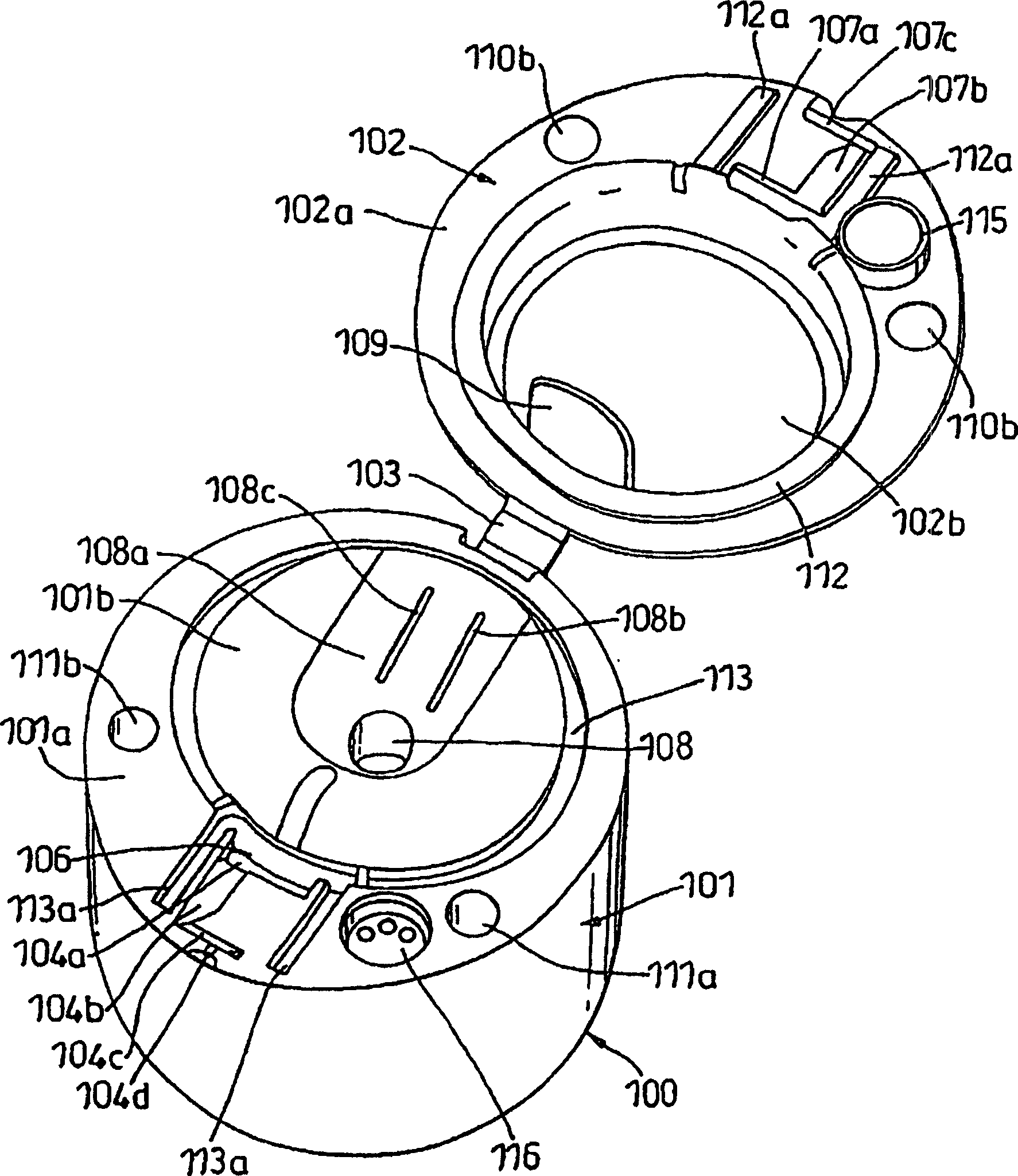
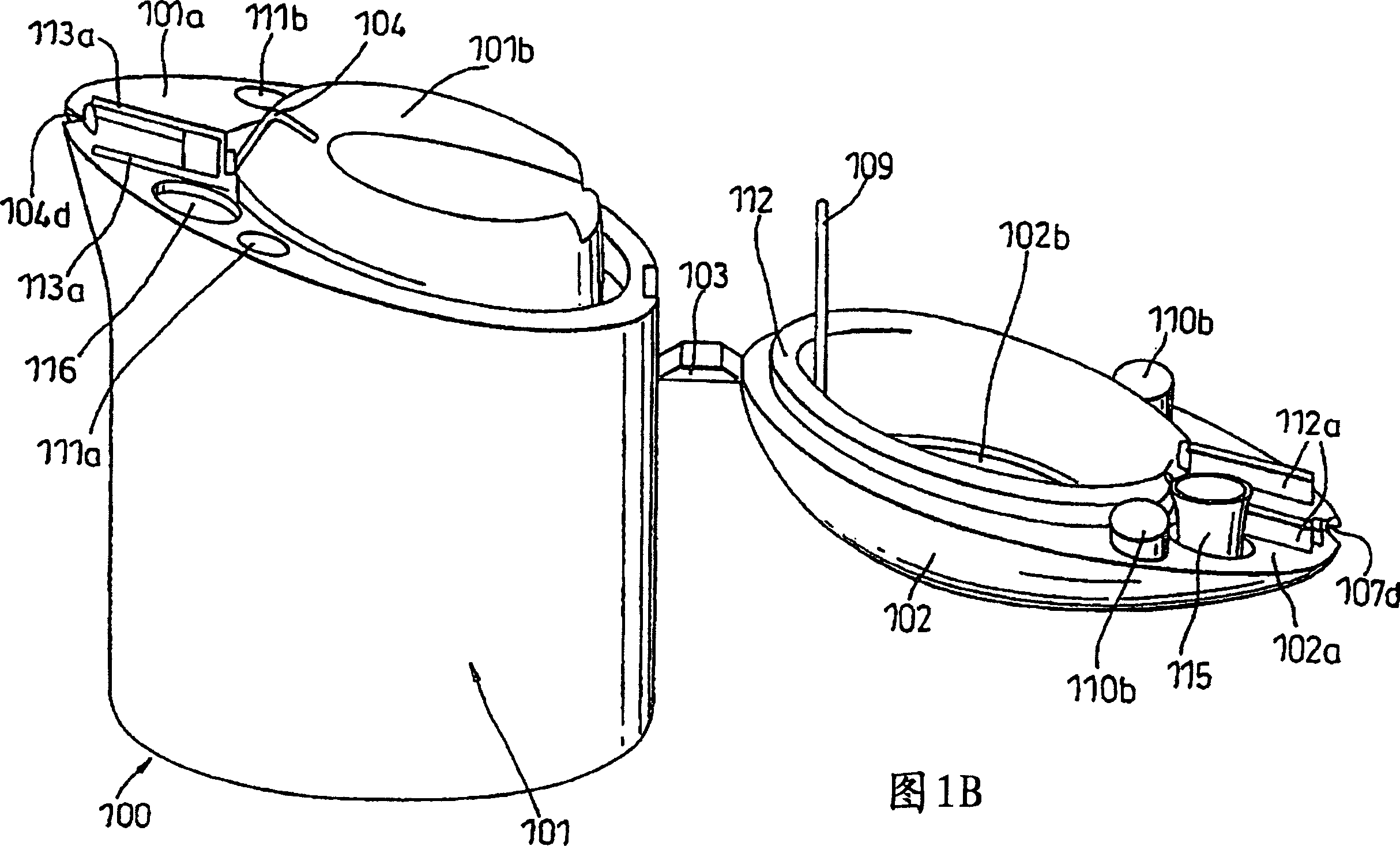
[0171] attached Figure 1A The nozzle device shown in and 1B comprises a main body 100 comprising two parts, namely a base 101 and an upper part 102 , which are interconnected by foldable connectors 103 .

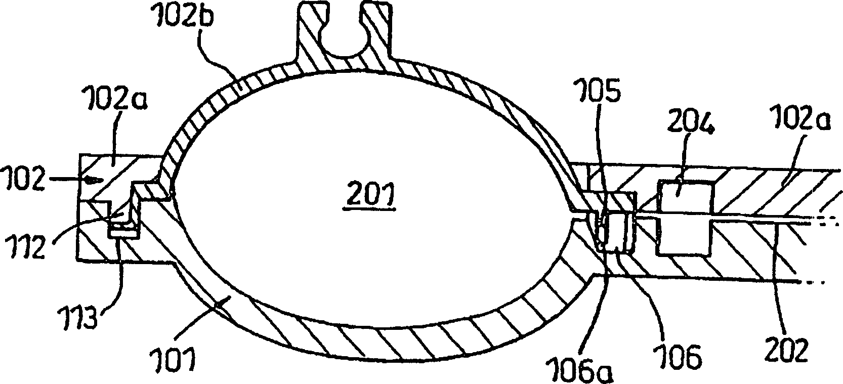
[0172] Body 100 is formed from a single rigid plastic in a single molding operation. The device is accompanied by Figure 1A and 1B, the upper part 102 is then folded around the connector 103 and fitted onto the upper surface of the base 101 to form an assembled nozzle structure. Once the base 101 and upper part 102 are fitted together, a portion 102a of the lower surface of the upper part 102 abuts an adjoining portion / surface 101a of the upper surface of the base 101 . The raised portion 101b of the upper surface of the base 101 is received in a groove 102b formed in the lower surface of the uppe...


PUM


Abstract

The present invention relates to a pump-action nozzle arrangement and a method of making such a nozzle arrangement. The nozzle device of the present invention includes a body defining an interior chamber having an inlet and an outlet through which fluid can flow into the chamber and through which fluid present in the chamber can escape from the chamber Nozzle discharges. The inlet includes an inlet valve and the outlet includes an outlet valve. Fluid can be dispensed from the dispenser nozzle by applying pressure to an actuator that engages and elastically deforms or moves a portion of the device body defining the chamber, thereby compressing the chamber and urging Fluid is dispensed. In a preferred embodiment, the actuating member provides a rigid actuating surface to which the operator can apply pressure.

Description

technical field [0001] The present invention relates to a nozzle arrangement and more particularly but not exclusively to a pump action nozzle and a method of manufacturing such a nozzle arrangement. Background technique [0002] Pump-action nozzle devices are generally used to provide a device by which fluid can be dispensed from a non-pressurized container. [0003] Traditional pump action nozzle assemblies tend to be extremely complex in design and often include multiple components (typically 8 to 10 individual components in pump nozzle assemblies and 10 and 14 individual components in trigger actuated nozzle assemblies) . As a result, these devices are expensive to manufacture because of the amount of material required to form the individual components, and the assembly process involved. Furthermore, many conventional devices tend to be bulky (which again increases raw material costs), and often a portion of this volume is disposed inside the container to which the dev...

Claims


Application Information

Patent Timeline
Patent Type & Authority Applications(China)
IPC IPC(8): B05B11/00
CPCB05B11/1032B05B11/1011
Inventor K·莱德勒T·罗德
Owner INCRO LTD
Features
  • R&D
  • Intellectual Property
  • Life Sciences
  • Materials
  • Tech Scout
  • Unparalleled Data Quality
  • Higher Quality Content
  • 60% Fewer Hallucinations
Learn More