Motor vehicle steering device
A technology for vehicles and steering systems, applied to steering columns, steering controls mounted on vehicles, mechanical equipment, etc., can solve the problems of click and impact noise and the level of sliding resistance cannot meet the standard value, and achieve low cost Effect
- Summary
- Abstract
- Description
- Claims
- Application Information
AI Technical Summary
Problems solved by technology
Method used
Image

Examples
no. 1 example
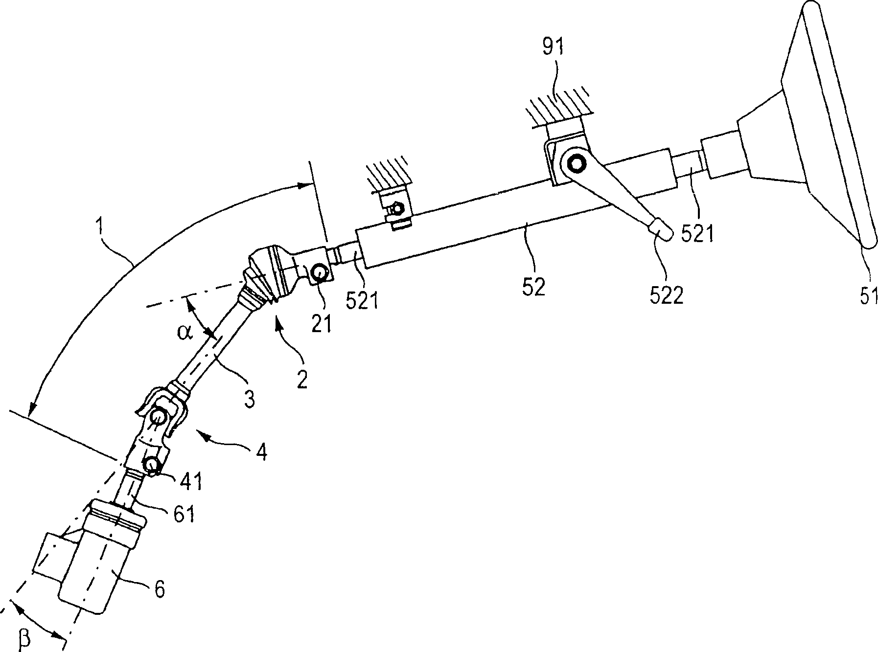
[0047] figure 1 It is an explanatory diagram showing the whole of the vehicle steering mechanism to which the present invention is applied. This figure shows a portion including the body-side steering mechanism 6 and its upward direction. The steering column tube 52 is fixed to the vehicle body 91 in such a manner that the inclination angle of the steering column tube 52 can be adjusted by adjusting the lever 522 . The steering column tube 52 rotatably supports a wheel shaft 521 passing therethrough, and the steering wheel 51 is fixed to an upper end of the wheel shaft 521 . The coupling system 1 is connected to the other end of the wheel shaft 521 or to the lower end side of the steering column tube 52 .
[0048] The coupling system 1 includes a constant velocity ball joint 2 arranged at its upper end, a cross shaft type universal joint 4 arranged at its lower end, and an intermediate shaft 3 arranged in the middle part therebetween for connecting the thus arranged universa...
no. 2 example
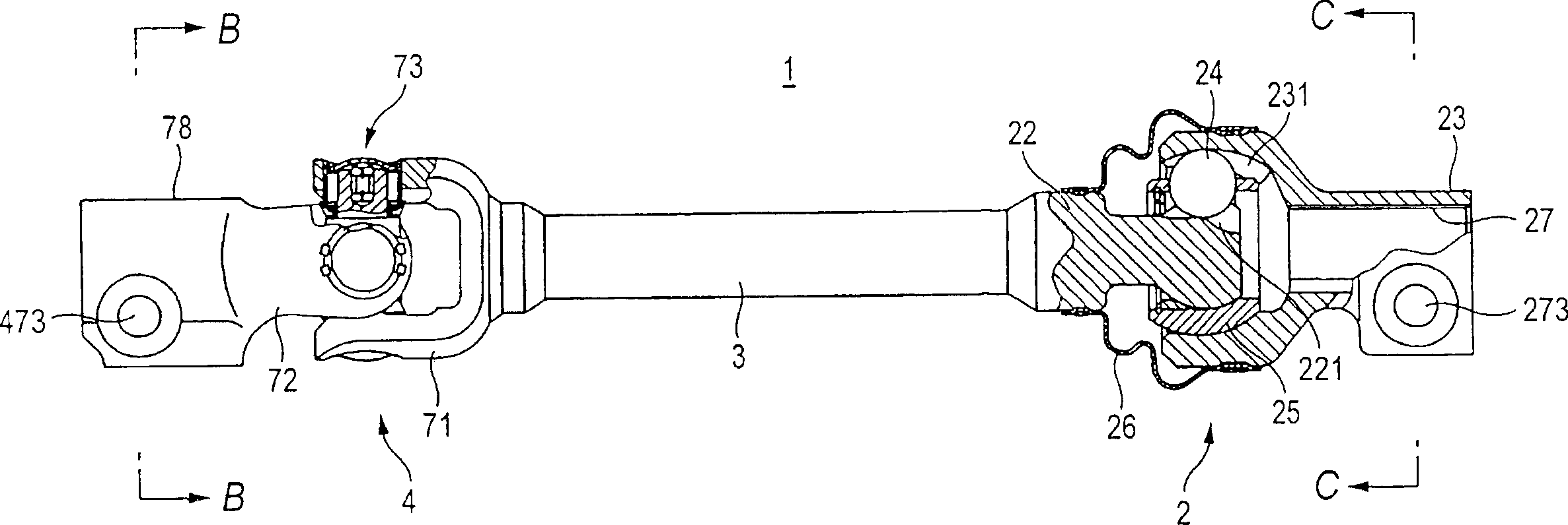
[0060] image 3 is a partial sectional view illustrating the coupling system 1 of the second embodiment. Hereinafter, only the points different from the first embodiment will be described, and other places and image 3 The description of the sectional view made by the line B-B, C-C can refer to the description of the first embodiment. These differ in that the intermediate shaft 3 consists of a partial shaft divided into two halves, the upper intermediate shaft 31 associated with the inner joint part 22 and the lower half associated with the cross joint 4 The intermediate shaft 32, and external splines 311 are formed on the upper intermediate shaft 31, and internal splines suitable for fitting on the external splines 311 are formed on the lower intermediate shaft 32.
[0061] The intermediate shaft 3 allows telescoping so that only rotation is transmitted through this splined connection. The telescoping property of the intermediate shaft 3 realizes a structure in which the p...
no. 3 example
[0066] Figure 4 It is an explanatory diagram showing the whole of the vehicle steering mechanism to which the present invention is applied. This figure shows a portion including the body-side steering mechanism 6 and its upward direction. The steering column tube 52 is fixed to the vehicle body 91 in such a manner that the inclination angle of the steering column tube 52 can be adjusted by adjusting the lever 522 . A wheel shaft 521 passing through the inside of the steering column tube is rotatably supported in the steering column tube 52 , and the steering wheel 51 is fixed at an upper end of the wheel shaft 521 . The intermediate shaft system 1 is connected to the other end of the wheel shaft 521 or to the lower end side of the steering column tube 52 .
[0067] The intermediate shaft system 1 includes constant velocity spherical joints 2, 4 at its upper and lower ends, and an intermediate shaft 3 connecting these joints to each other at an intermediate portion therebetw...
PUM
 Abstract
Description
Claims
Application Information
 - R&D
- Intellectual Property
- Life Sciences
- Materials
- Tech Scout
- Unparalleled Data Quality
- Higher Quality Content
- 60% Fewer Hallucinations
Browse by: Latest US Patents, China's latest patents, Technical Efficacy Thesaurus, Application Domain, Technology Topic, Popular Technical Reports.
© 2025 PatSnap. All rights reserved.Legal|Privacy policy|Modern Slavery Act Transparency Statement|Sitemap|About US| Contact US: help@patsnap.com