
Identification device for medical equipment and patients

A technology of medical technology and accessories, which is applied in the field of devices for identifying medical technology accessories and patients, and can solve problems such as human error

Inactive Publication Date: 2006-07-19
SIEMENS AG
View PDF0 Cites 0 Cited by
  • Summary
  • Abstract
  • Description
  • Claims
  • Application Information

AI Technical Summary

Problems solved by technology

Correspondence by professionals, with all the care that can be afforded, is subject to human error

Method used


Image

  • Identification device for medical equipment and patients

Examples


Embodiment Construction

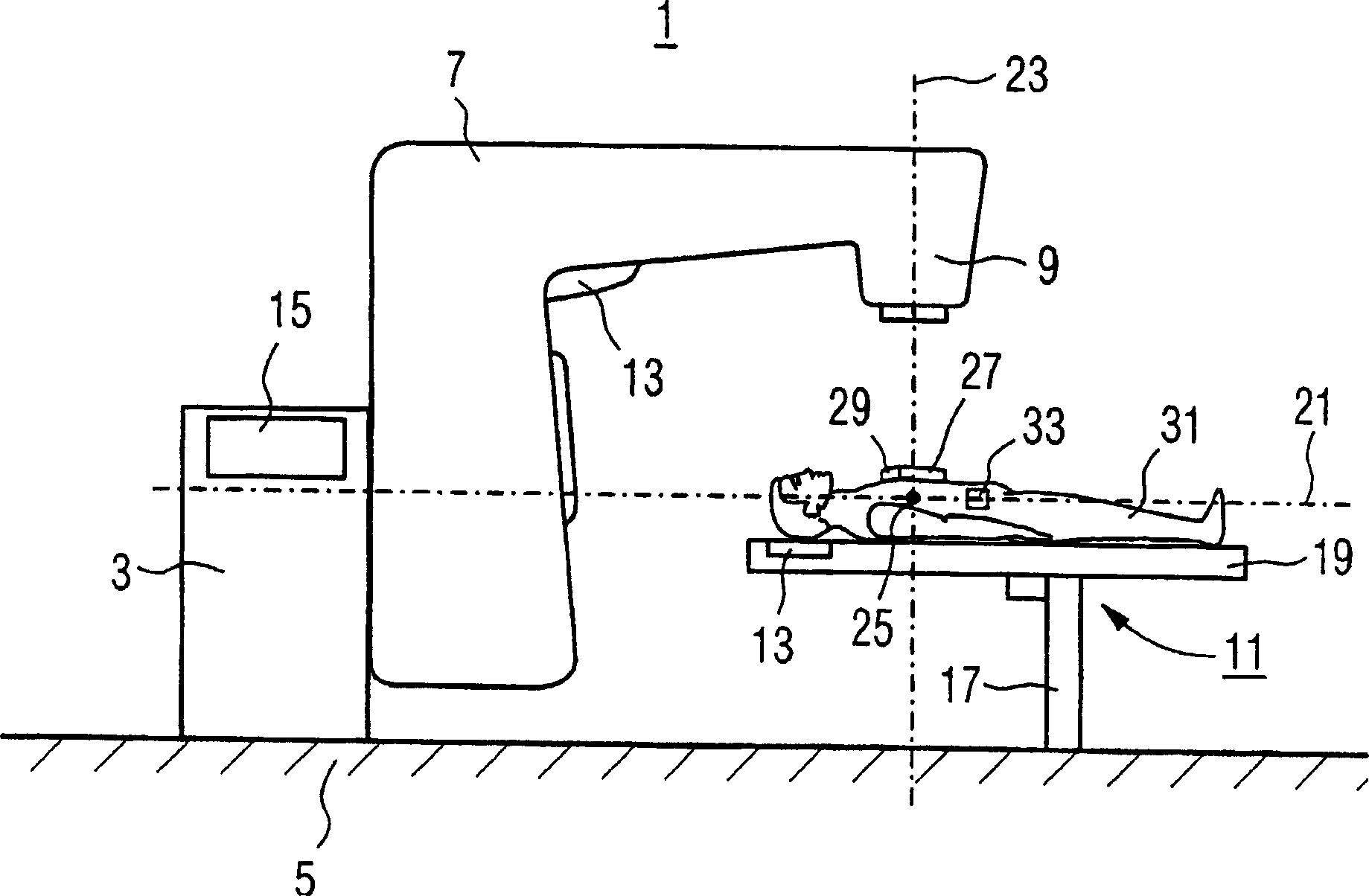
[0027] exist figure 1 A radiotherapy apparatus 1 for delivering therapeutic radiation to a patient 31 is shown in . The radiotherapy apparatus 1 has an arcuate column 3 against which the radiotherapy apparatus rests and on which a bracket 7 is fixed. The support 7 carries a radiation source 9 emitting ionizing radiation.

[0028] The radiotherapy system 1 also includes a patient support device 11 with a patient couch 19 . The patient couch, on which the patient 31 to be irradiated lies, is supported in a height-adjustable manner by lifting columns 17 .

[0029] The ionizing radiation travels from the radiation source 9 along a vertical coaxial axis 23 towards the patient 31 . Depending on the radiation used and its penetration depth, the position of the horizontal coaxial axis 21 in which the radiation acts can be given. At the intersection of the horizontal coaxial 21 and the vertical coaxial 23 is the so-called therapeutic concentric 25 in which the radiation exhibits it...


PUM


Abstract

The invention relates to a device for identifying medical equipment and patients. Said device comprises a transponder-reading apparatus (13) and a control unit (15) that is connected thereto. The transponder-reading apparatus (13) is configured so as to be able to read out a patient transponder (33) and an equipment transponder that is mounted on a piece of medical equipment. The control unit (15) is configured so as to be able to pick up data which the transponder-reading apparatus (13) reads out of an equipment transponder as an input signal and generate an equipment identification signal according to said input signal while being able to pick up data which the transponder-reading apparatus (13) reads out of a patient transponder (33) as an input signal and generate a patient identification signal according to said input signal. The inventive device can be part of a radiation therapy system while the piece of medical equipment can be a radiation mask. Also disclosed is a system for identifying medical equipment, comprising a control unit (15), a transponder-reading apparatus (13) that is connected to the control unit (15), and an equipment transponder which is mounted on a piece of medical equipment.

Description

technical field [0001] The invention relates to a device for identifying medical technology accessories and patients. Background technique [0002] Automatic identification of objects is known, for example by means of barcode systems. A barcode provided on an item is read by a laser-based reading device and used, for example, to identify the item. This system is used in shopping malls or logistics control devices and the like. [0003] In addition to barcodes, so-called transponders are used, which do not operate by means of optical reading devices, but are based on RF (radio frequency) transmission. The reading device transmits electrical energy via RF to the transponder, which can thus reflect a reply signal back to the reading device without its own power supply. In the transponder there is non-volatile memory which contains the information to be sent to the reading device. [0004] Compared with barcode systems, transponder systems have the advantage that they are ea...

Claims


Application Information

Patent Timeline
Patent Type & Authority Applications(China)
IPC IPC(8): G06K7/00G06K19/07G06K19/077A61B5/00A61B5/117A61B6/08A61N1/372A61N5/10
CPCG06K7/0008A61N2005/1074A61B5/0002G06K19/0723A61B5/117A61B6/4494A61B6/08G06K19/07758A61N5/10G06K19/07749
Inventor 安德烈·希尔纳斯蒂芬·莱登伯格斯蒂芬·格利斯曼马克·沃福德
Owner SIEMENS AG
Learn More