Display with rotatable image pick-up assembly
A technology for image capture and display, applied to color TV parts, TV system parts, instruments, etc., can solve problems such as loosening and damage, shortening the service life of mechanical components, etc.
- Summary
- Abstract
- Description
- Claims
- Application Information
AI Technical Summary
Problems solved by technology
Method used
Image

Examples
Embodiment Construction
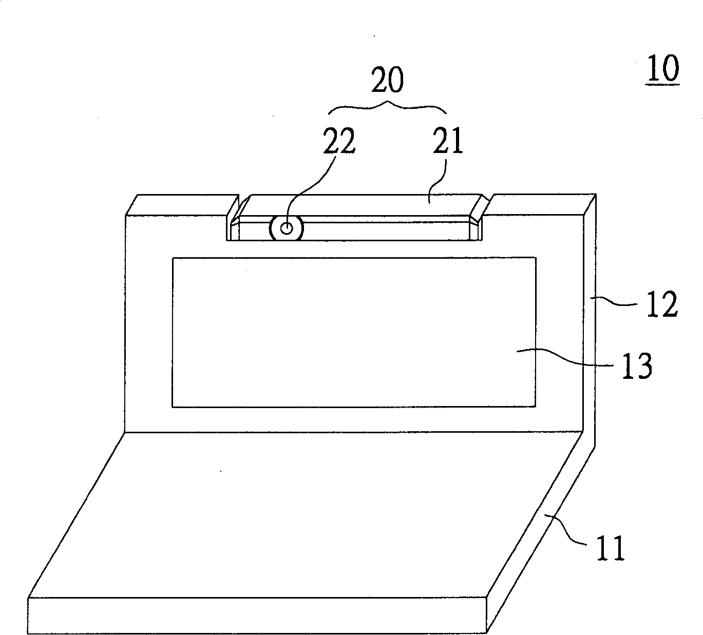
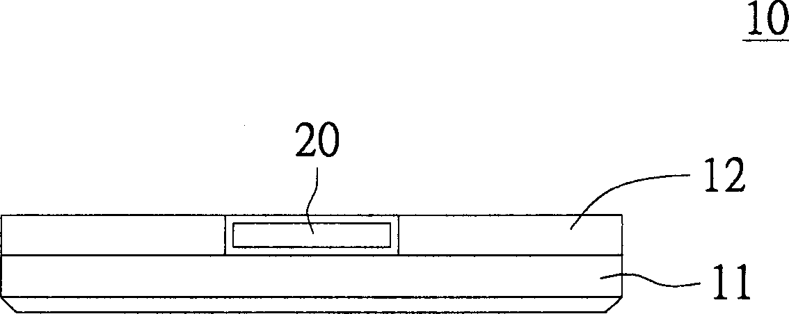
[0022] The main idea of the present invention is to provide a display with a rotatable image capture unit, which has a protective shell design, which can avoid unnecessary movement and damage to the image capture unit when opening and closing. Wherein, the image capture component of the present invention includes a second casing and an image capture unit. The second casing is fixedly connected to the first casing of the display, and the second casing has an opening. The two ends of the image capture unit are respectively pivotally connected to the mouth wall of the opening, whereby the image capture unit is rotatably arranged in the display.
[0023] The main idea of the present invention is to propose a rotatable image capture unit. Its two-stage positioning design allows the image capture unit to be fixed at several specific angles and positions, so as to facilitate the use and storage of images by users. Fetch components. Wherein, the image capture component of the pr...
PUM
 Abstract
Description
Claims
Application Information