Substrate transferring apparatus

A substrate transfer equipment and substrate technology, applied in lighting and heating equipment, conveyors, conveyor objects, etc., can solve the problems of increased manufacturing costs, complex structure of substrate transfer equipment, and difficult management of conduits

Inactive Publication Date: 2006-08-02
SFA CO LTD
View PDF0 Cites 21 Cited by
  • Summary
  • Abstract
  • Description
  • Claims
  • Application Information

AI Technical Summary

Problems solved by technology

[0005] However, since such an air-floating type substrate transfer device requires a pump to supply high-pressure air to float the substrate and a conduit to connect the pump to the body of the substrate transfer device, the substrate transfer device has

Method used


Image

  • Substrate transferring apparatus
  • Substrate transferring apparatus
  • Substrate transferring apparatus

Examples


Embodiment approach 1

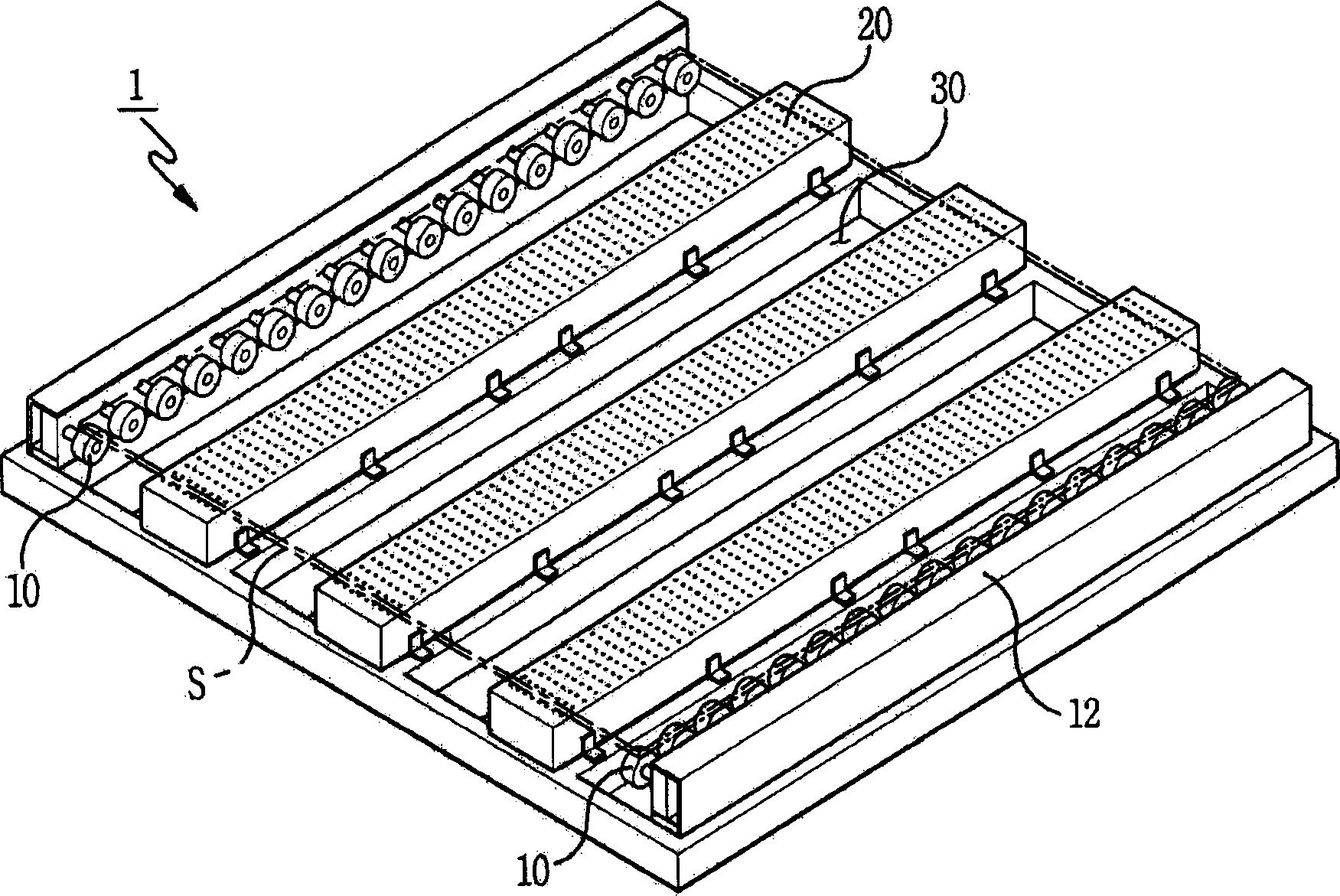
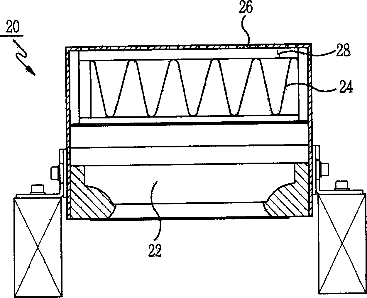
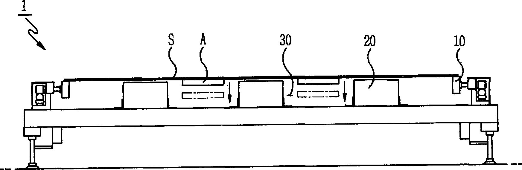
[0021] Such as figure 1 As shown, the substrate transfer apparatus 1 according to the first embodiment includes a pair of transfer roller devices 10 , a plurality of air injection modules 20 , and a plurality of substrate loading and unloading channels 30 .

[0022] The pair of transfer roller devices 10 are in direct contact with both ends of the substrate S, and rotate to transfer the substrate S in a horizontal direction. In order for the substrate to be conveyed by the pair of conveying roller assemblies 10 with a very narrow portion on both sides of the substrate in contact with the pair of conveying roller assemblies 10, the conveying roller assemblies 10 are spaced apart as far as possible in the horizontal direction. . At this time, the transport roller device 10 is rotated by an isolated driving unit (not shown). Here, the driving unit is separated from the pair of transfer roller devices 10 in order to prevent particles that may be generated during the rotation of ...

Embodiment approach 2

[0035] Such as Figure 6 As shown, the substrate transfer apparatus 100 according to the second embodiment includes a substrate moving part 110 and a plurality of air injection modules 120 . According to the second embodiment, the substrate is transferred in an inclined state instead of a horizontal state to reduce the footprint of the substrate transfer apparatus 100 . Here, the substrate is conveyed obliquely at a predetermined angle instead of being conveyed upright, thereby ensuring higher stability when conveying the substrate. When the substrate is transferred obliquely at a predetermined angle, the substrate is supported by the plurality of air injection modules 120 at one side thereof. This allows the substrate to be stably transferred without dropping, and reduces the space occupied by the substrate transfer apparatus 100 in the clean room.

[0036] The substrate moving part 110 is used to move the substrate in the horizontal direction while maintaining the substrat...


PUM


Abstract

Disclosed herein is a substrate transferring apparatus. The apparatus comprises air injection modules, which serve to float a substrate, and can be independently attached to or detached from the substrate transferring apparatus. Thus, even if any one of the air injection modules is damaged, the substrate is prevented from falling because other air injection modules serve to continuously float the substrate. Furthermore, with such a construction, the air injection modules have an advantage in view of maintenance.

Description

technical field [0001] The present invention relates to a substrate conveying apparatus for conveying plate-like substrates. Background technique [0002] Recent developments in information technology have led to widespread use of information display devices, and demand for them continues to grow. Various information display devices are known in the prior art, ranging from conventional CRT monitors to flat panel displays such as liquid crystal displays (LCDs), plasma display panels (PDPs), and light emitting diodes (OLEDs). In particular, LCDs have grown in importance for applications because of their practicality. In particular, due to the advantages of small size, light weight, and low power consumption, LCDs have been increasingly used to overcome disadvantages of conventional displays such as CRT monitors and as a substitute for conventional displays. [0003] In the production process of such flat panel display devices, a thin glass substrate with a thickness of about...

Claims


Application Information

Patent Timeline
IPC IPC(8): B65G49/06B65G51/02
Inventor 郑准模李正洙
Owner SFA CO LTD
Why Eureka
Try Eureka