Electricity generating techn with marine energy, water energy and wind energy
A wind power generation and ocean technology, which is applied in the directions of ocean power generation, wind turbines, wind turbine combinations, etc., can solve the problems of insufficient exploration, underutilization and high cost of renewable wind energy generation.
- Summary
- Abstract
- Description
- Claims
- Application Information
AI Technical Summary
Problems solved by technology
Method used
Image

Examples
Embodiment 1
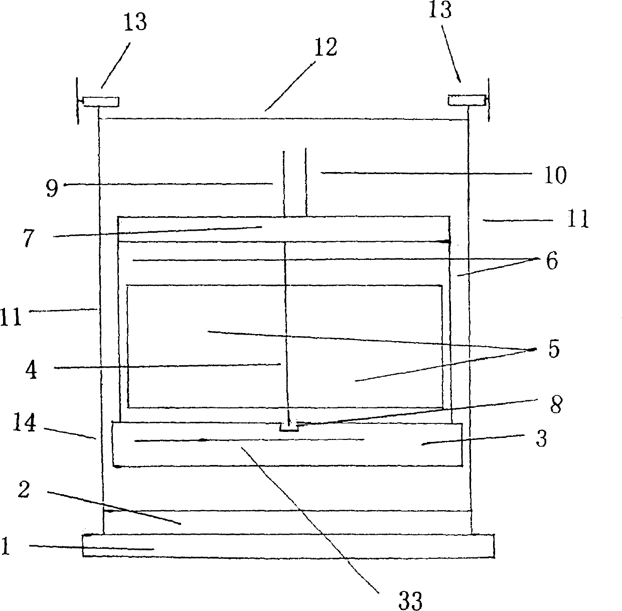
[0032] Embodiment one. See figure 1 , figure 2 , image 3 , Figure 4 , Figure 5 , Figure 6 , Figure 7 , Figure 8 , Figure 9 , Figure 10 , Figure 11 , Figure 12 , Figure 16 .
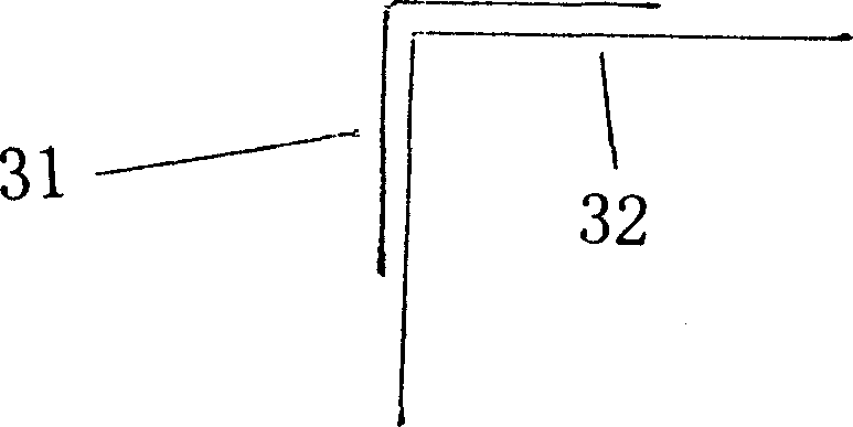
[0033] Floating tank (3) is a cube shape. It can be filled with water through the pipe (33) to make it sink. Also the pipe of water pump can be put into buoyancy tank from pipe (33), the water wherein is extracted out and it floats. When pipe (33) is not used at ordinary times, after sealing, such as figure 1 fixed on the buoy. The length of the pipe is determined as required. Base (1) is made of concrete, also can make with other material that can resist seawater corrosion. Four columns (11) are arranged on the four corners of the base (1). The shape of the column see figure 2 (31) in. Four columns just limit four angles of pontoon like this. In order not to get stuck between the pontoon and the column, try to make the contact space between them looser. There are baffl...
Embodiment 2
[0043] Embodiment two. According to the principle of the new turbine in the first embodiment, that is, because the front and back sides of the vanes of the new turbine receive different forces in the running water, the new turbine can always rotate in one direction in the running water. In practice, specific forms of new turbines are determined according to needs, which are used for fluid energy generation such as water energy and ocean energy.
Embodiment 3
[0044] Embodiment three. See Figure 13 , Figure 14 , Figure 15 . The vane of the new turbine is set to be flat. The principle is to make the vanes of the new turbine perpendicular to the flowing water, make the axis of the vortex theory parallel to the water surface, and make the flowing water directly impact the vanes to rotate around the axis. Thereby driving the generator to generate electricity. But currents such as waves in the ocean, unlike those in rivers, often change direction. Therefore, the buoyant tank should be designed to be cylindrical, and the circular area of the buoyant tank should be greater than the projection of equipment such as new turbines and generators on it. Simultaneously, on the buoyancy tank, a large plate thing is established perpendicular to the axis of the new turbine. The bases are arranged in a circular shape together. The pedestal is the same with uprights limiting the pontoon. If currents such as ocean waves are not perpendicu...
PUM
 Abstract
Description
Claims
Application Information
 - R&D
- Intellectual Property
- Life Sciences
- Materials
- Tech Scout
- Unparalleled Data Quality
- Higher Quality Content
- 60% Fewer Hallucinations
Browse by: Latest US Patents, China's latest patents, Technical Efficacy Thesaurus, Application Domain, Technology Topic, Popular Technical Reports.
© 2025 PatSnap. All rights reserved.Legal|Privacy policy|Modern Slavery Act Transparency Statement|Sitemap|About US| Contact US: help@patsnap.com