Optical glass material for moulding

An optical glass and molding technology, applied in the field of optical glass materials for molding, can solve the problems of excellent surface quality, high roughness and high adhesion of carbon film

Inactive Publication Date: 2006-08-09
ASIA OPTICAL CO INC
View PDF2 Cites 0 Cited by
  • Summary
  • Abstract
  • Description
  • Claims
  • Application Information

AI Technical Summary

Problems solved by technology

In addition, because the carbon film deposited by the method disclosed in Japanese Patent Application Laid-Open No. 63-222023 has high adhesion and high roughness, it is difficult to remove the carbon film remaining on the glass during the subsequent tempering process after molding. The carbon film on the surface of the lens prevents the final glass lens from obtaining excellent surface quality

Method used


Image

  • Optical glass material for moulding
  • Optical glass material for moulding
  • Optical glass material for moulding

Examples


specific Embodiment

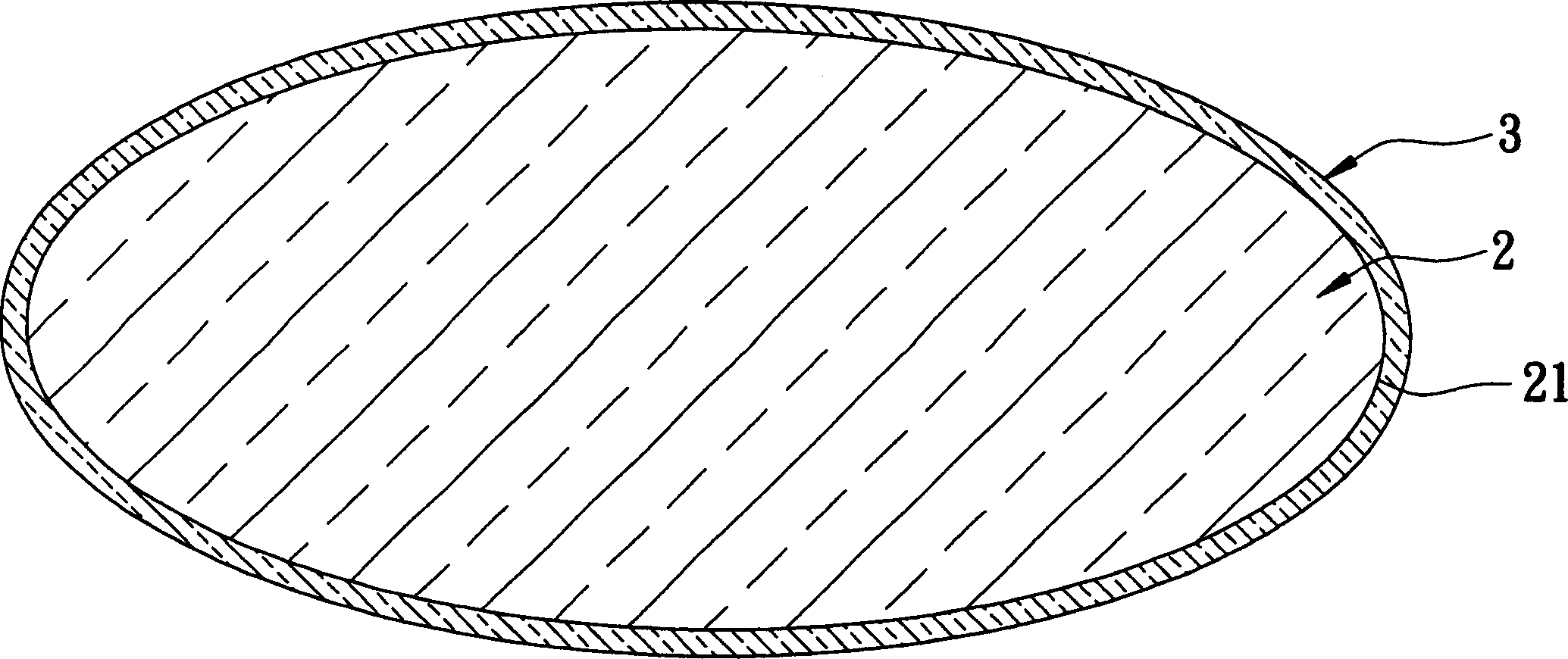
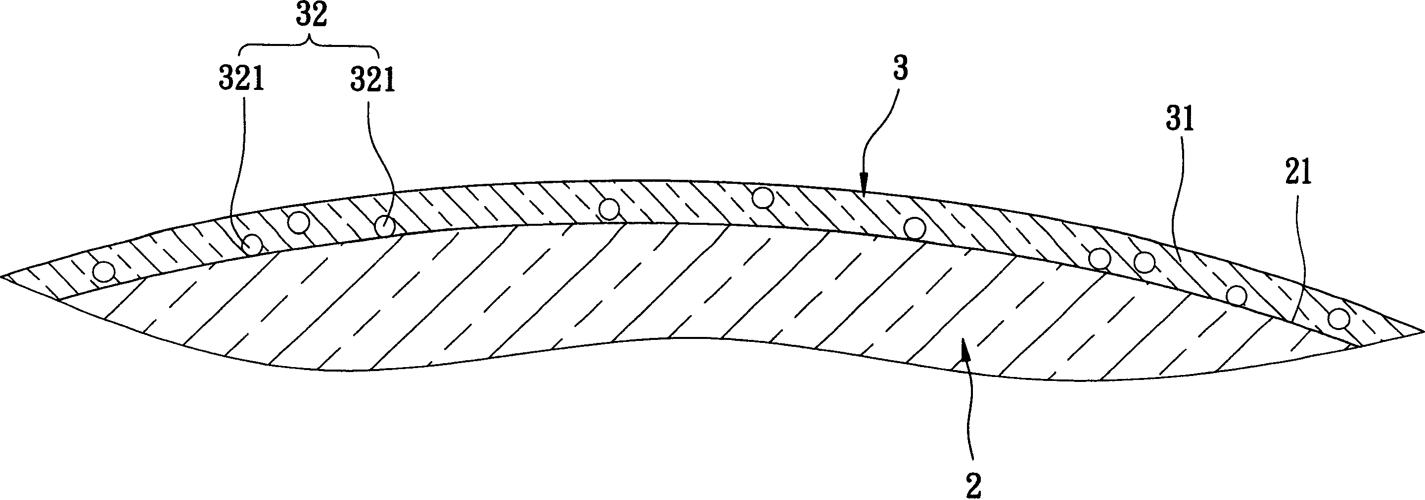
[0028]In a specific embodiment of the optical glass material for molding of the present invention, the matrix layer 31 of the protective film 3 is a matrix layer of amorphous carbon, and the diffusion unit 32 is composed of a component containing silicon and carbon, containing silicon and Oxygen components, and components containing silicon, carbon and oxygen are made. Therefore, in this specific embodiment, the nanoparticles 321 are composed of three kinds of nanoparticles: nanoparticles containing silicon and carbon (Si-C), nanoparticles containing oxygen and silicon (Si-O), and nanoparticles containing silicon , carbon and oxygen (Si-C-O) nanoparticles.

[0029] In this specific embodiment, the model produced by Nisho OHARA is L-LBAL35 and T g The glass raw material with a temperature of 527° C. is used as the glass body 2 . The manufacturing method of the optical glass material for molding in this specific embodiment of the present invention is briefly described below. ...


PUM


Abstract

The invention discloses a model using optical glass material that includes glass body, and protection film, which as a basal material layer and dispersing unit. The basal material layer is the cohort selected from the amorphous carbon, diamond carbon or the combination of them.

Description

technical field [0001] The invention relates to a glass material, in particular to an optical glass material for molding. Background technique [0002] In the field of optical glass lenses, the general molding technology for making optical glass lenses is mainly to form a glass material preform by grinding a glass raw material so that the glass material has an appearance similar to the molded product, and the glass material The preform is cleaned. Subsequently, the glass material preform is placed in a mold set for glass molding, and the mold set is heated to a softening point (soft point) or a temperature close to the softening point, so that the glass material disposed in the mold set The preform is softened and shaped into a glass lens having a forming surface opposite the mold set. [0003] In general, the molding method of the aforementioned optical glass lenses is to directly contact the exposed glass material preform with the forming surface of the mold set. The ph...

Claims


Application Information

Patent Timeline
IPC IPC(8): C03C17/22
Inventor 王坤池王清华
Owner ASIA OPTICAL CO INC
Why Eureka
Try Eureka