
Eureka
For R&D, Eureka makes reading and utilizing patents & technical documents easy.
Eureka AIR
Designed for self-driven R&D workflows. Generate viable solutions, solve complex R&D challenges, empower your innovation with AI.

Eureka Materials
Designed for material experts only. Revolutionize your material R&D, from search, analyze, to developing new materials.

TechResearch
Generate reliable direction feasibility study reports for your R&D in just a few steps.

TechSeek
Discover and master advanced knowledge NOW. Basics, ideas, possibilities, all at once.

TechMind
As an expert in R&D Theories, TechMind can generates customized viable solutions instantly.

TechRisk
Analyze your overall solution with one click, know your potential R&D risks in advance.

TechMonitor
Get weekly tech updates, stay abreast of the latest tech innovations and key insights.
Floor drain
A floor drain and flange installation technology, which is applied to indoor sanitary pipeline installations, waterway systems, drainage structures, etc., can solve the problems of heavy tight connections, difficult and impossible floor drains, etc., and achieve a good airtight effect
- Summary
- Abstract
- Description
- Claims
- Application Information
AI Technical Summary
Problems solved by technology
Method used
Image

Examples
Embodiment Construction
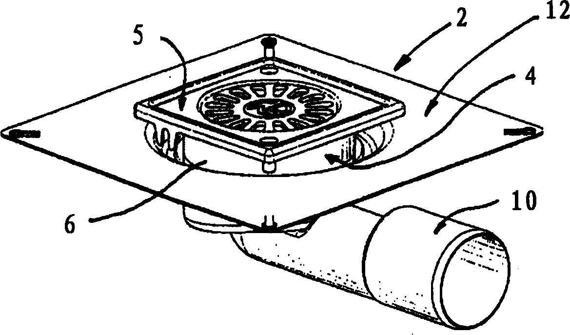
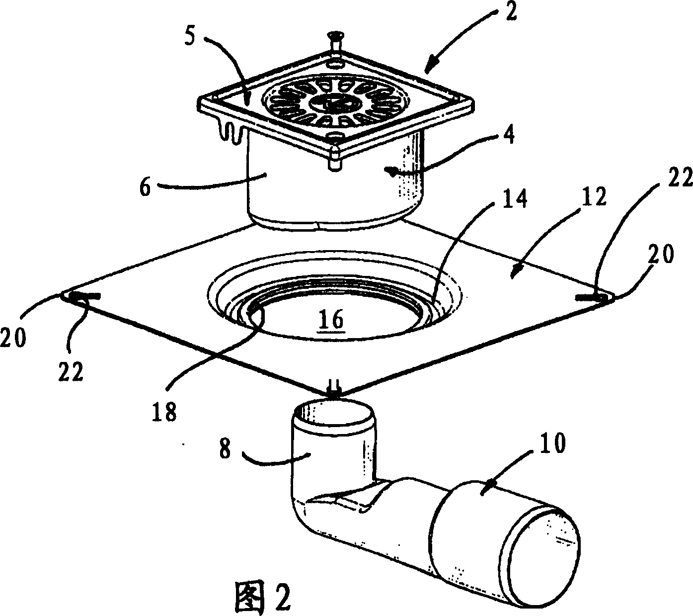
[0022] exist figure 1 The floor drain 2 shown at - 2 comprises a drain cover 4 with a cylindrical outer side 6 . The drain cover 4 can comprise a water reservoir, not shown, with a centrally located lower drain hole, into which the vertical connection part 8 of the elbow connection pipe 10 can be fitted by means of a suitable filling tool. The floor drain 2 is provided with a square drainage grid 5 at the top.
[0023] In addition, the floor drain 2 also includes a mounting flange 12 which has a connection hole 16 with a circular filling tool 18 at the centrally bent tab portion 14, so that the loosened mounting flange 12 can be mounted on the drain cover 4 in a watertight manner. On the predetermined height outside cylindrical outer 6. Alternatively, it is also possible to use a circular filling tool which is fixed in the connecting hole 16 by vulcanization.
[0024] As clearly shown in FIG. 2, the mounting flange 12 is mounted on the cylindrical outer side 6 of the drain ...
PUM
 Abstract
Description
Claims
Application Information
 - R&D Engineer
- R&D Manager
- IP Professional
- Industry Leading Data Capabilities
- Powerful AI technology
- Patent DNA Extraction
Browse by: Latest US Patents, China's latest patents, Technical Efficacy Thesaurus, Application Domain, Technology Topic, Popular Technical Reports.
© 2024 PatSnap. All rights reserved.Legal|Privacy policy|Modern Slavery Act Transparency Statement|Sitemap|About US| Contact US: help@patsnap.com