Piston with pressure-reducing piston ring

A technology of piston rings and piston ring grooves, applied in the directions of piston rings, pistons, engine components, etc., can solve the problems of large energy consumption and large friction loss, and achieve the effect of reducing energy consumption, reducing frictional resistance, and improving energy conversion efficiency.

Inactive Publication Date: 2006-08-16
廖伯成
View PDF0 Cites 2 Cited by
  • Summary
  • Abstract
  • Description
  • Claims
  • Application Information

AI Technical Summary

Problems solved by technology

[0004] The purpose of the present invention is to solve the problem of large friction loss and large energy consumption due to the ring back thrust of the piston ring in the existing piston reciprocating engine, and to provide a method that can reduce the ring back thrust of the piston ring. , enhance the effect of sealing and air-tightness, greatly reduce friction loss, and achieve the purpose of energy saving. Piston with decompression piston ring

Method used


Image

  • Piston with pressure-reducing piston ring
  • Piston with pressure-reducing piston ring
  • Piston with pressure-reducing piston ring

Examples


Embodiment 1

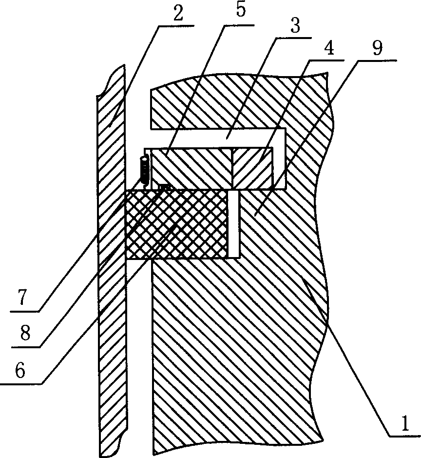
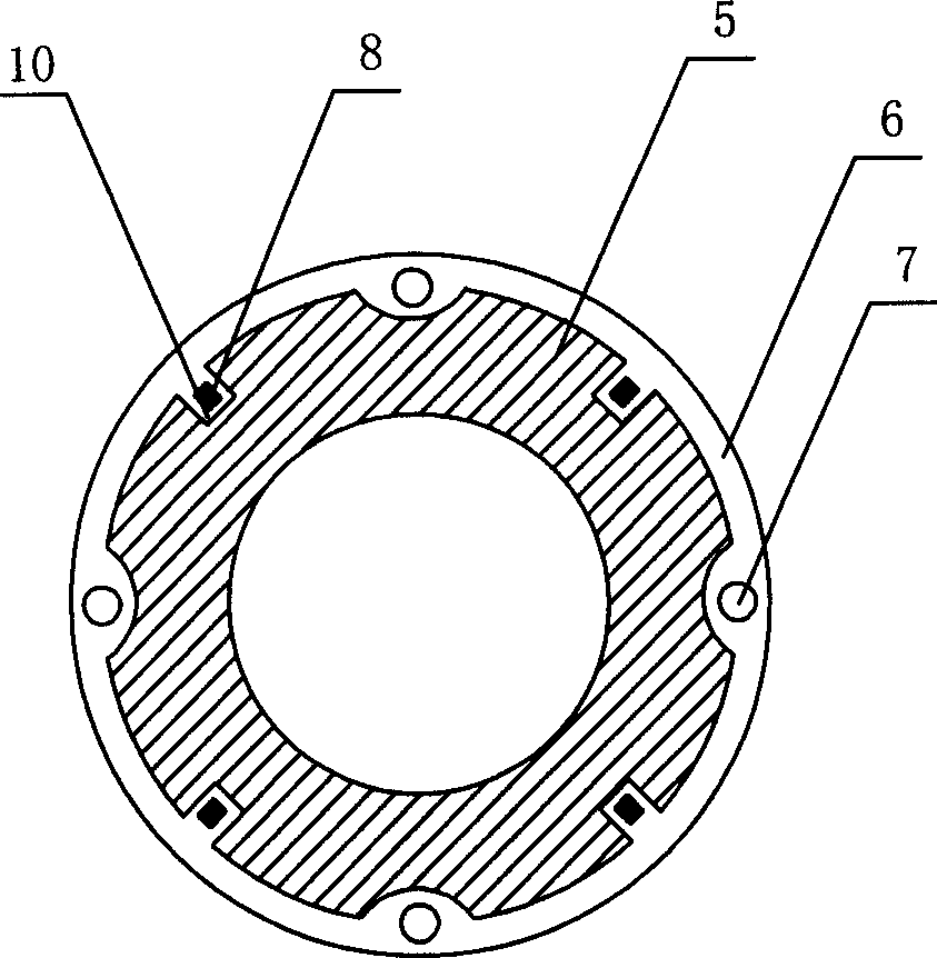
[0062] Embodiment 1: as figure 1 , figure 2 As shown, the piston with a decompression piston ring includes a piston body 1, a piston ring groove 3 on the piston body 1, and a piston ring in the piston ring groove 3, and the piston body 1 with the piston ring is set in the cylinder 2. The piston ring groove 3 is a stepped annular groove with two different groove depths, the upper groove depth is larger, and the lower groove depth is small, so a step 9 is formed on the piston body 1 . The piston ring is divided into an outer ring 5 arranged in the upper section of the piston ring groove 3, an inner ring 4 sleeved in the outer ring 5, and an outer tension ring 6 arranged in the lower section of the piston ring groove 3. The outer ring 5 and the inner ring 4 have the same thickness, but the thickness of both is less than the height of the upper section of the piston ring groove 3, and the inner diameter of the inner ring 4 is larger than the diameter of the piston body 1 at the ...

Embodiment 2

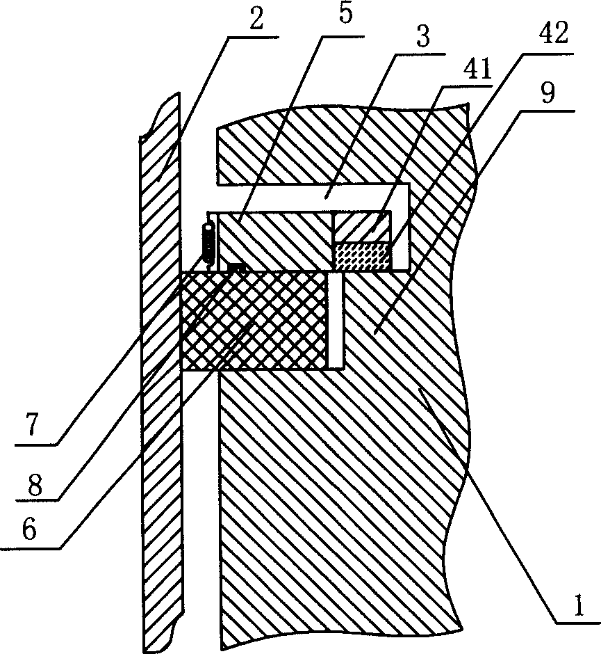
[0066] Embodiment 2: as image 3 As shown, the basic structure is the same as in Embodiment 1, wherein the inner ring 4 is composed of an inner first ring 41 and an inner second ring 42 of the same size stacked up and down.

Embodiment 3

[0067] Embodiment 3: as Figure 4 As shown, the basic structure is the same as that in Embodiment 2, wherein the outwardly stretched ring 6 is composed of a first outwardly stretched ring 61 and a second outwardly stretched ring 62 stacked up and down. There is a triangular notch on the outside of the cross-section of the first ring 61 and the inner wall of the cylinder 2. The outer side of the upper end surface is in contact with the inner wall of the cylinder 2, and the lower end of the spring 7 is fixed on the upper end surface; The diameter of the inner wall of 2 is equivalent, the outer diameter of the lower end surface is equivalent to the outer diameter of piston body 1, and its cross-section is an upwardly inclined flat head oblique cone.


PUM


Abstract

The invention relates to an engine piston, which includes a piston body, a piston ring groove disposed on the piston body and a piston ring disposed in the piston ring groove. The piston ring groove consists of the upper and lower notches. An inner ring and an outer ring are disposed in the upper notch. A externally-braced ring is disposed in the lower notch.

Description

technical field [0001] The invention relates to a piston of an engine, in particular to a piston with a decompression piston ring which can reduce the pressure of the piston ring on the inner wall of the cylinder. Background technique [0002] Since the invention of the piston reciprocating internal combustion engine, after more than one hundred years of rapid development, its fuel economy is still very low. In addition to the heat loss accounting for more than 60%, the piston and piston ring are due to the transmission of the connecting rod during the power stroke. The side pressure and the back thrust applied to the piston ring by the expansion work of the high-pressure gas further aggravate the wear of the piston ring and the inner wall of the cylinder. The working ability of the fuel oil greatly reduces the thermal efficiency of the internal combustion engine, and this problem has not been effectively solved. According to the related data and the research on the wear de...

Claims


Application Information

Patent Timeline
Patent Type & Authority Applications(China)
IPC IPC(8): F02F3/00F02F5/00
Inventor 廖伯成
Owner 廖伯成
Why Eureka
Try Eureka