Yarn arrangement device and method for yarn arrangement using the device, yarn arrangement tool, method of manufacturing yarn arranged body, and method of manufacturing living body-related substance i
A technology of fiber arrangement and related substances, which is applied in the field of fiber winding body and fiber arrangement body, and manufacturing fiber arrangement body, which can solve the problems of difficulty in fiber insertion into holes, deterioration of fiber rigidity, and fiber arrangement.
- Summary
- Abstract
- Description
- Claims
- Application Information
AI Technical Summary
Problems solved by technology
Method used
Image

Examples
example 1
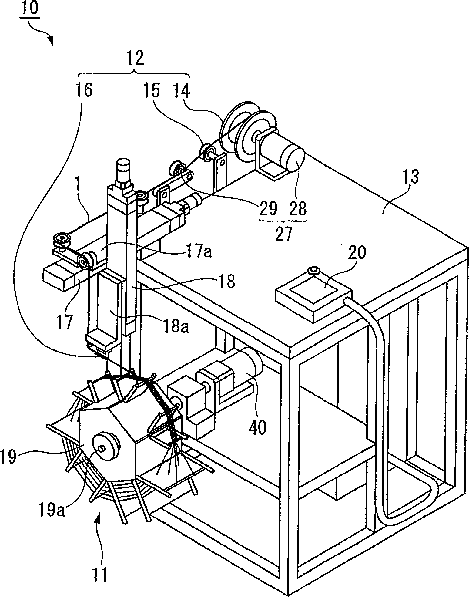
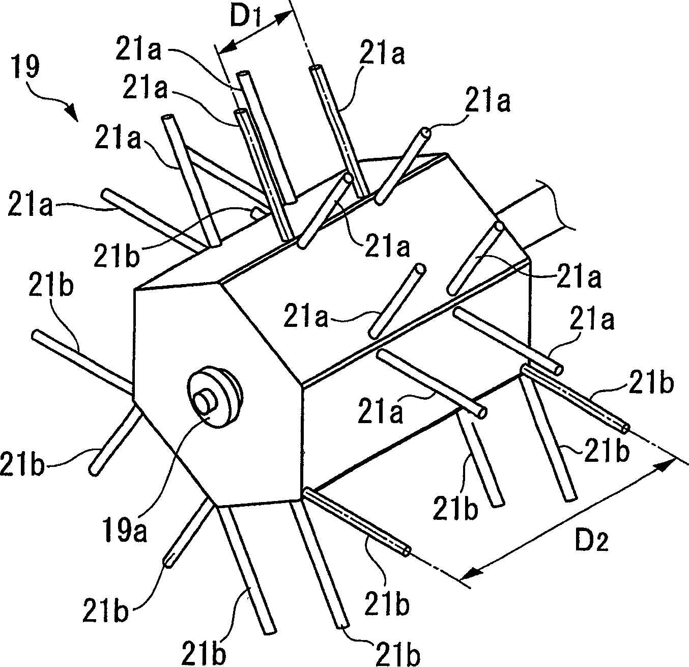
[0170] using its structure with figure 1 Fiber alignment device 10 of the same construction is shown, but omitted entirely Figure 4B Wide spaced plates 22b are shown and only 120 are provided Figure 4A The fine pitch plate 22a is shown, and only twelve sets (ie, 24 in total) of fine pitch struts 21a are erected as fiber take-up spools. Using this fiber arranging device 10, a fiber winding body in which polycarbonate hollow fibers having a diameter of 0.3 mm are arranged in 10 rows by 10 layers can be obtained.
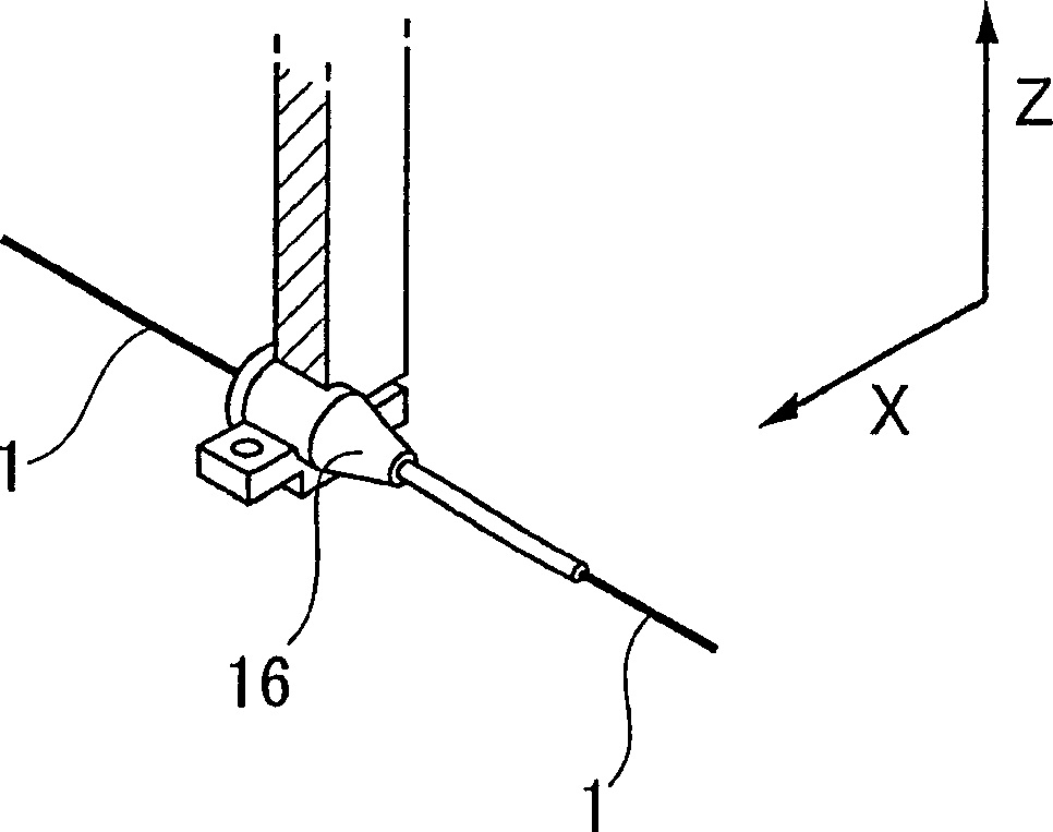
[0171] It should be noted that the moving speed of the nozzle-shaped movable guide 16 in the X-axis direction was set to 12000 mm / min, and the moving pitch was set to 0.42 mm, which was the same pitch between the grooves 23a in the fine pitch plate 22a. A tension of 5 mN was applied to the hollow fibers arranged in this way by a tension application device. In addition, the minimum distance (ie, the gap) between the distal end of the movable guide 16 and the groove...
example 2
[0174] use figure 1 The fiber alignment device 10 shown, for example Image 6 Shown is a fiber winding body 30 in which polycarbonate hollow fibers having a diameter of 0.3 mm are arranged in 10 rows by 10 layers.
[0175] It should be noted that the moving speed of the nozzle-shaped movable guide 16 in the X-axis direction was set to 12000 mm / min. The moving distance of the precision-pitch plate 22a is set to 0.42mm, which is the same as the distance between the grooves 23a in the precision-pitch plate 22a; The pitches between the grooves 23b in 22b are the same. A tension of 5 mN was applied to the hollow fibers arranged in this way by a tension application device. In addition, the minimum distance (ie, the gap) between the end of the movable guide 16 and the concave strips 23a and 23b of the fiber alignment flat plates 22a and 22b in which fibers from the movable guide 16 are arranged is set to be constant 0.5 mm. The rotational speed of the fiber winding spool 19 was s...
example 3
[0178] Two positions on the portion sandwiched between the two laminated bodies 25 of the fine pitch flat plate 22a in the fiber winding body 30 obtained in Example 2 were placed as follows Figure 9 Perfusion block 36 shown. like Figure 10 Then, a solution of polyurethane elastomer (coronate 4403 / nippolan 4276 mixed in the ratio of coronate 6:nippolan 4) was injected into the hollow part and hardened, thereby obtaining Figure 11 status shown. Then, the fiber 1 is cut and the fiber arrangement flat plates 22a and 22b are appropriately removed. As a result, the fiber 1 can be prepared from the single fiber winding body 30 to Figure 7 The two bulk fiber arrays 32 are precisely arranged in the manner shown. The required working time is approximately one hour until the resin solution is poured.
PUM
| Property | Measurement | Unit |
|---|---|---|
| thickness | aaaaa | aaaaa |
| width | aaaaa | aaaaa |
| length | aaaaa | aaaaa |
Abstract
Description
Claims
Application Information
 - R&D Engineer
- R&D Manager
- IP Professional
- Industry Leading Data Capabilities
- Powerful AI technology
- Patent DNA Extraction
Browse by: Latest US Patents, China's latest patents, Technical Efficacy Thesaurus, Application Domain, Technology Topic.
© 2024 PatSnap. All rights reserved.Legal|Privacy policy|Modern Slavery Act Transparency Statement|Sitemap