

Band washing unit and band washing method
A cleaning device and technology for strips, applied in the field of strip material cleaning, can solve problems such as poor cleanliness, and achieve the effect of improving cleanliness
- Summary
- Abstract
- Description
- Claims
- Application Information
AI Technical Summary
Problems solved by technology
Method used
Image

Examples
no. 1 specific Embodiment approach
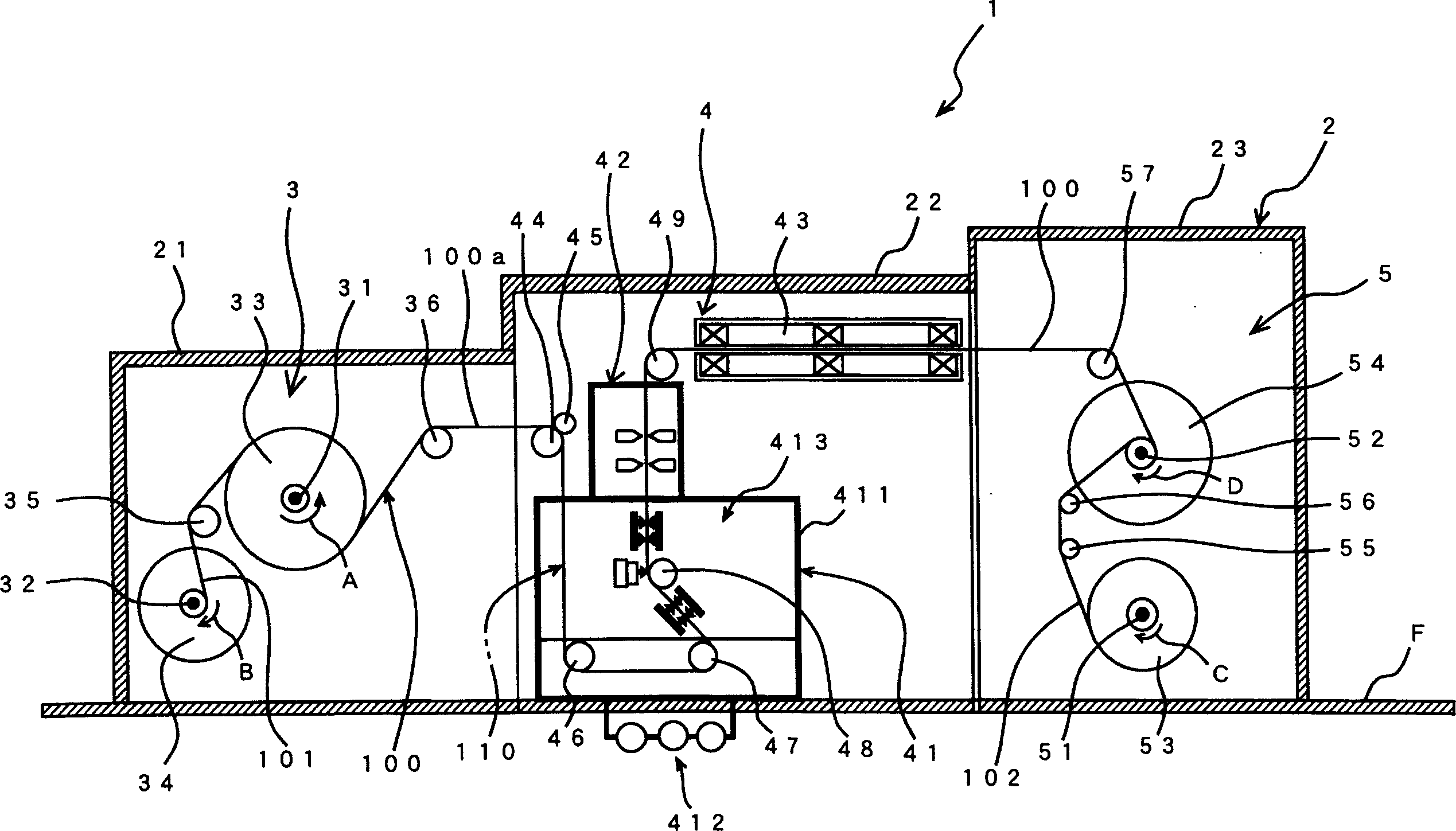
[0118] figure 1 It is a schematic diagram of the strip cleaning device 1 according to the first embodiment of the present invention. This cleaning device 1 is a cleaning device for a film carrier tape 100 for a TAB tape. Among them, in a specific embodiment, the film carrier tape 100 is simply referred to as the tape 100 for description below.
[0119] Described strip cleaning device 1, device 1 is integrally arranged in clean room R, comprises: the clean room 2 that is arranged on the floor F of clean room R; Mechanism 3, strip cleaning mechanism 4, strip storage mechanism 5; a control device (illustration omitted) arranged on the floor F outside the clean room 2. In addition, the clean room 2 may not be provided, and the strip supply mechanism 3, the strip cleaning mechanism 4, the strip storage mechanism 5 and the control device are directly installed in the clean room R to form a strip cleaning device.
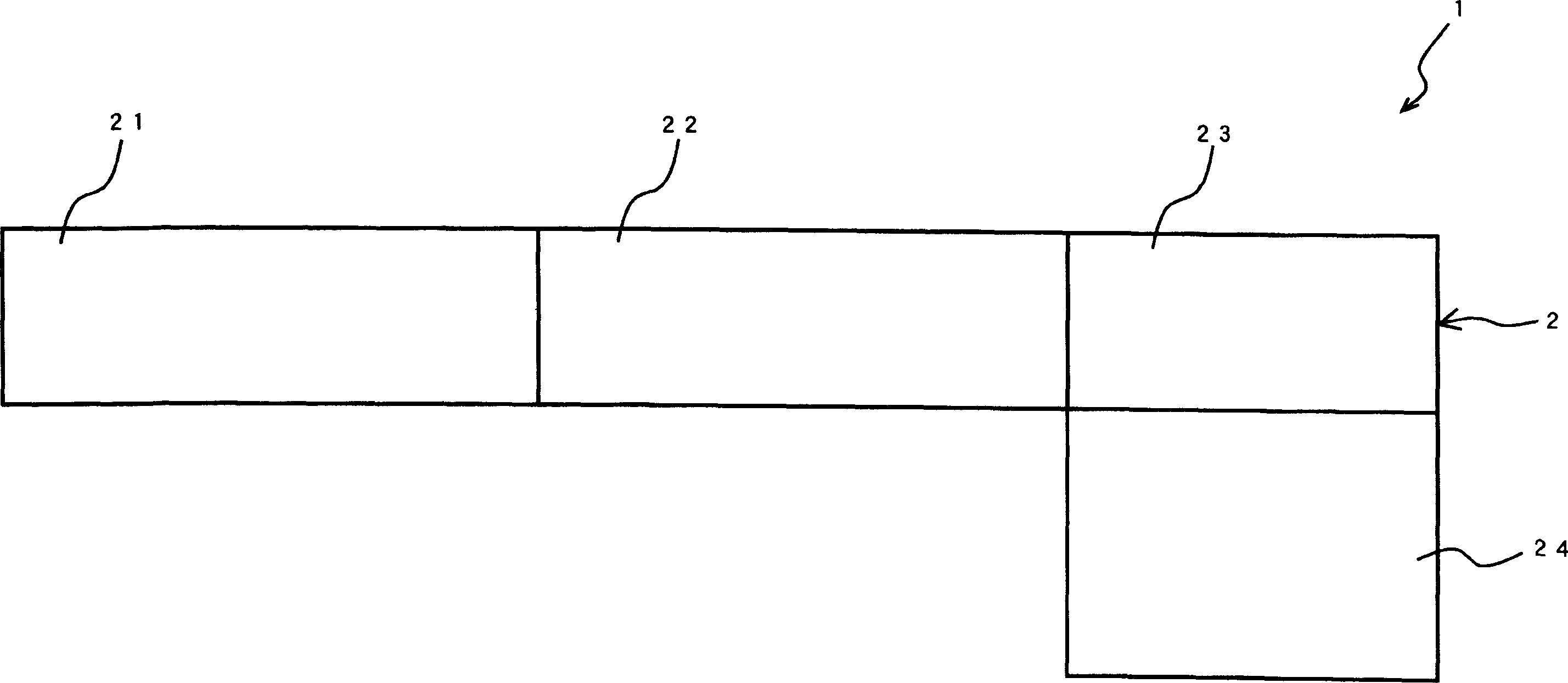
[0120] Such as figure 2 As shown, the clean room 2 includes: thr...
no. 2 specific Embodiment approach
[0210] Figure 4 It is a partial schematic diagram of a tape cleaning device 200 according to a second embodiment of the present invention. In this specific embodiment, the same parts as those in the first specific embodiment are denoted by the same symbols, and the different parts will be mainly described.
[0211] The strip cleaning device 200 of this specific embodiment has three guide wheels 47, 240, 241 that guide the strip 100 soaked in the soaking tank 411 back to the horizontal direction, and the front cleaning mechanisms 4131, 4131 clean through these guide wheels. 47, 240, 241 convey the strip 100 in the horizontal direction.
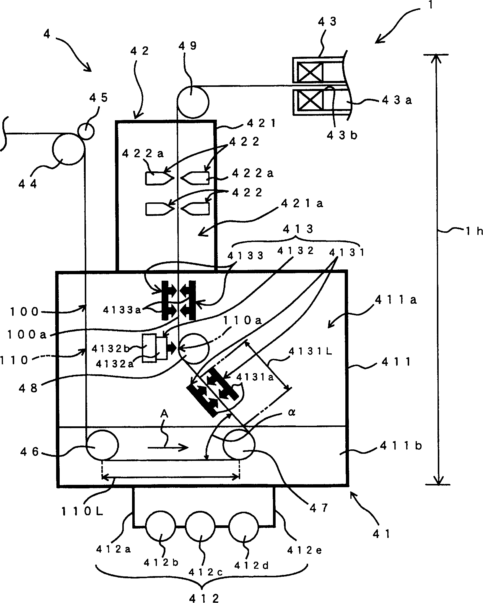
[0212] With the above configuration, compared with conveying the soaked strip 100 upward, the conveyance area of the strip 100, in other words, the height 200h of the cleaning device 200 can be made smaller than that of the cleaning device described in the first embodiment. 1 height 1h (see image 3 ) is controlled to be lower. Therefore...
no. 3 specific Embodiment approach
[0215] Figure 5 It is a partial schematic diagram of a strip cleaning device 300 shown in the third embodiment of the present invention. In this specific embodiment, the same parts as those in the first specific embodiment are denoted by the same symbols, and the different parts will be mainly described.
[0216] In the strip cleaning device 300 of this specific embodiment, the fixing mechanism of the present invention is composed of three guide wheels 348 arranged vertically and separately along the conveying line 100a.
[0217] With the above structure, compared with the guide wheel 48 of the first embodiment and the guide wheel 241 of the second embodiment, since the number of guide wheels is increased, the contact distance with the strip 100 can be ensured to be longer, and the strip can be moved The material 100 is stably fixed on the conveying line 100a.
[0218] Therefore, even if the cleaning liquid is sprayed from the ultrasonic mechanism 4132 to the strip 100 , sh...
PUM
 Abstract
Description
Claims
Application Information