Appearance checking device and method

A visual inspection device, one-sided technology, applied in the direction of measuring device, image enhancement, instrument, etc.

Inactive Publication Date: 2006-09-06
OLYMPUS CORP
View PDF1 Cites 7 Cited by
  • Summary
  • Abstract
  • Description
  • Claims
  • Application Information

AI Technical Summary

Problems solved by technology

[0004] However, in conventional visual inspection equipment, when defects such as deformation, fine scratches, and dust adhesion occur in optical elements such as lenses and mirrors (illumination optical system), the illuminating light disturbed by the defect is irradiated onto the substrate surface. superior
The observer detects defects on the substrate surface by visually irradiating the substrate surface illuminated with illumination light, so it is impossible to identify whether the change in light appearing on the substrate surface is caused by a defect of the substrate itself or by a bad factor of the illumination optical system The problem
Therefore, there is a problem that a false defect image (false defect) caused by a defect in the illumination optical system is mistaken for a true defect of the substrate itself.

Method used


Image

  • Appearance checking device and method
  • Appearance checking device and method

Examples


Embodiment Construction

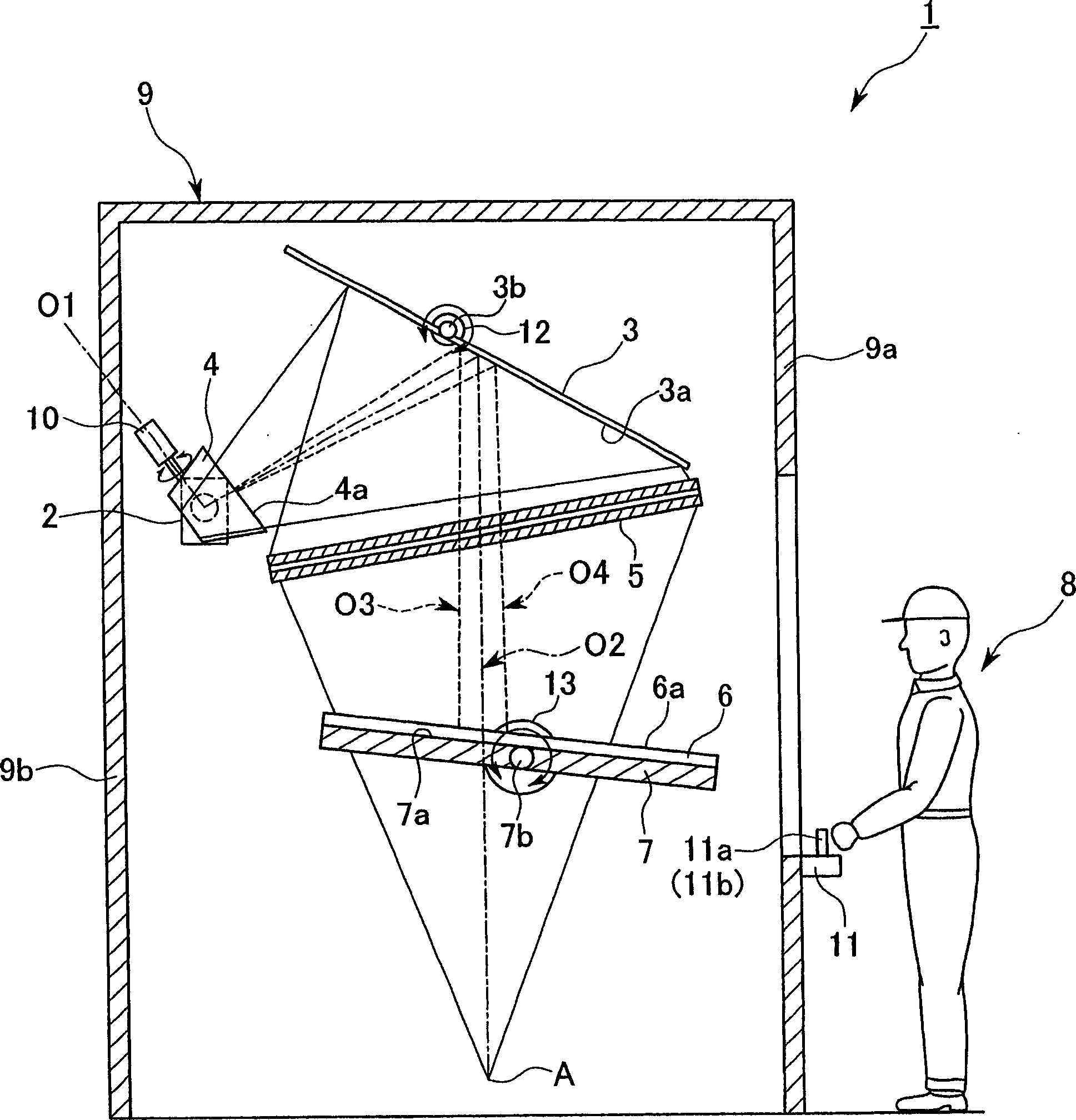
[0014] Below, refer to figure 1 The visual inspection device and visual inspection method according to the first embodiment of the present invention will be described.

[0015] The first embodiment of the present invention provides such figure 1 Shown, for example, is used for the appearance inspection apparatus 1 of the inspection of liquid crystal glass substrate, and this appearance inspection apparatus 1 is made up of the following parts for example: the light source 2 of metal halide lamp etc.; The light emitted by the light source 2 is deflected to the second reflector 3 side; the second reflector 3 (optical element), which deflects the light deflected by the first reflector 4 to the converging lens 5 side; the converging lens 5 (optical element), It condenses the light deflected by the second mirror 3 to irradiate the whole or part of the wide inspection area of ​​the surface 6a of the substrate 6; the substrate holder 7 is arranged under the converging lens 5, for exa...


PUM


Abstract

The invention relates to a testing device for appearance and the testing method. The said testing device can distinguish the false drawback cause by light source or optical element and the real drawback of base plate. The process is as that: said testing device (1) testing base plate by viewing the reflect light of illumination ray on surface (6a) of base plate, changing optical axis or focal point position through the periodical or free swinging or bending of optical element, of which comprises light source (2), and the second reflecting mirror (3) and the first reflecting mirror (4) or collective lens (5); then said false drawback will swing, through which realizes said distinguish.

Description

technical field [0001] The present invention relates to an appearance inspection device and an appearance inspection method for glass substrates such as liquid crystal displays. Background technique [0002] Conventionally, in the inspection of liquid crystal glass substrates, etc., the surface of the substrate is irradiated with light, and the observer visually observes the optical changes of the reflected light to confirm defects such as film streaks and pinholes of the resist coated on the surface. , Whether there is dust attached or not. As an appearance inspection device used for such an inspection, there is a device composed of: a reflective mirror that deflects light irradiated from a light source; A converging lens such as a Fresnel lens; and a substrate holder holding a substrate so that the low-magnification illumination light converged by the converging lens is irradiated onto the surface of the substrate (for example, refer to Patent Document 1). In this visual...

Claims


Application Information

Patent Timeline
Patent Type & Authority Applications(China)
IPC IPC(8): G01N21/88
CPCG01N21/15G01N21/55G01N21/88G01N2021/95638G02F1/13G06T2207/30141H05K3/0002
Inventor 冈平裕幸
Owner OLYMPUS CORP
Why Eureka
Try Eureka