Valve

A valve and valve body technology, used in sliding valves, valve devices, engine components, etc., can solve the problems that the performance parameters are difficult to meet the needs of industrial engineering, the design of the operating mechanism is complex, and the manufacturing cost is high. Fast, easy to process effects

Inactive Publication Date: 2006-09-20
潘世永 +2
View PDF3 Cites 9 Cited by
  • Summary
  • Abstract
  • Description
  • Claims
  • Application Information

AI Technical Summary

Problems solved by technology

However, since the open valve has two sealing surfaces, if the operating mechanism is in contact with the valve body on the transmission route of the pressure of the two valve plates before and after the valve is closed, it is easy to cause over-positioning problems, making the two sealing surfaces practical. Only one of them works, which makes the design of the internal operating mechanism of the va

Method used


Image

  • Valve
  • Valve
  • Valve

Examples


Embodiment 1

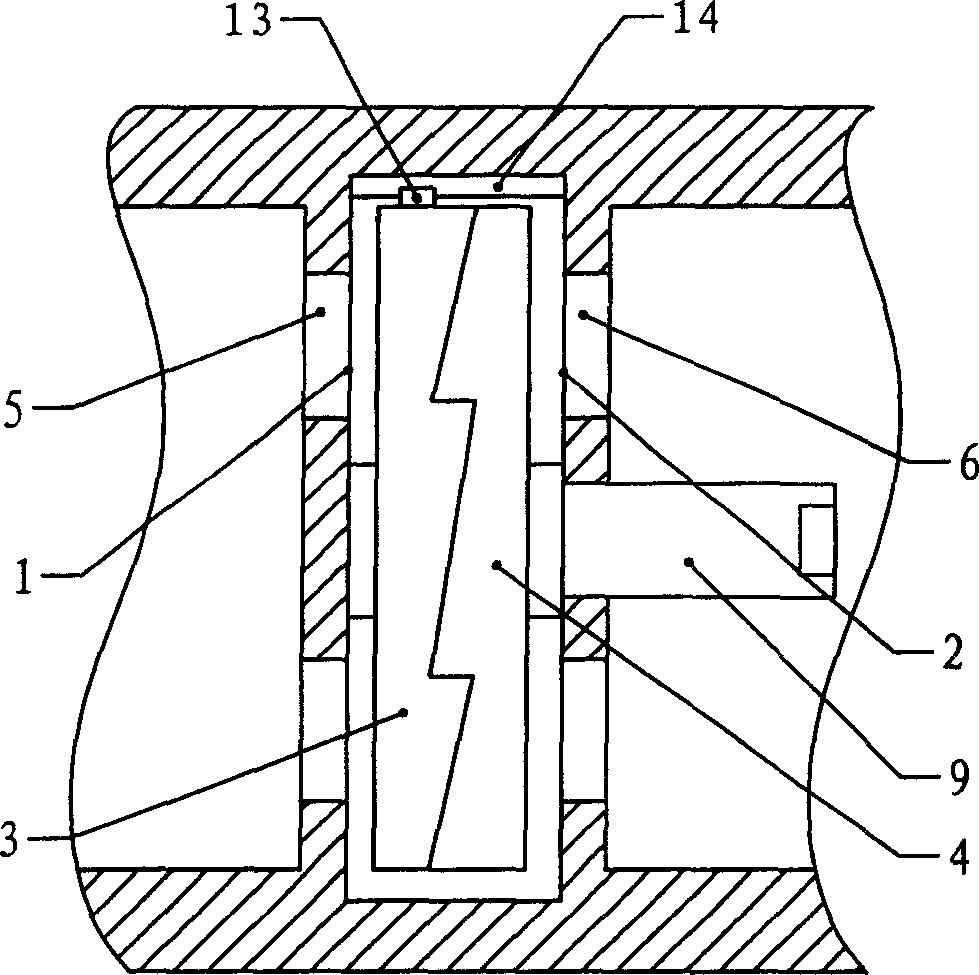
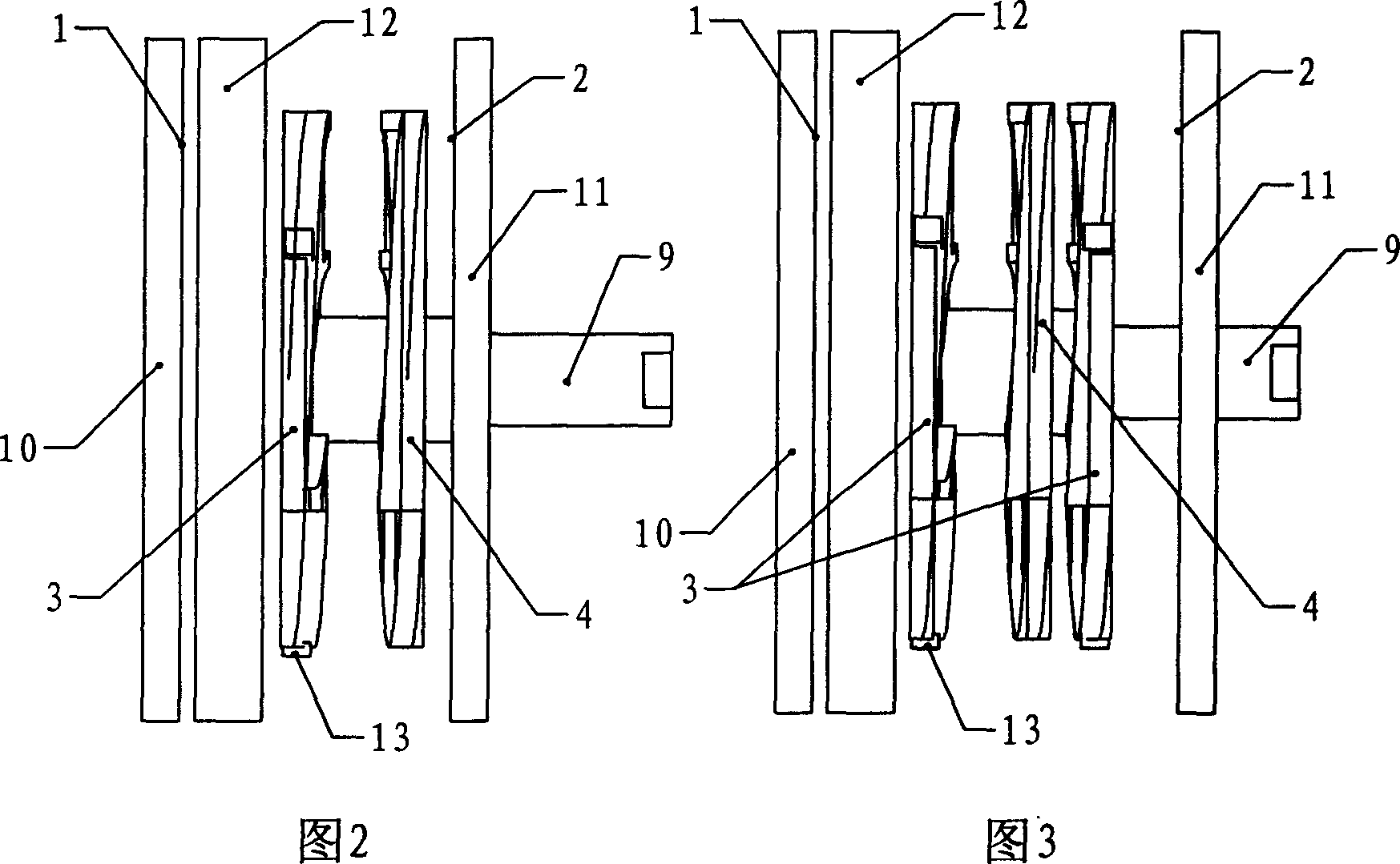
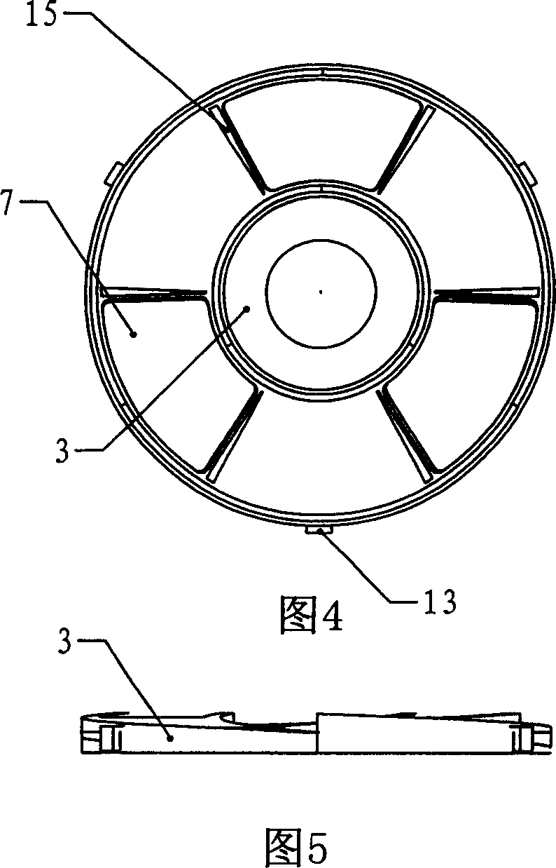
[0038] Embodiment 1: as shown in Fig. 2, 4~ Figure 11 As shown, the valve of the present invention includes a valve body provided with a sealing cavity. The lower pressing plate 10, the supporting ring 12 and the upper pressing plate 11 are sequentially stacked and connected with the valve body as a whole. The hollow part inside the supporting ring 12 forms a sealing cavity. The upper sealing surface 1 is arranged on the lower pressing plate 10, the lower sealing surface 2 is arranged on the upper pressing plate 11, and the inlet and outlet of the flow channel connecting the sealing cavity are respectively arranged on the lower sealing surface 1 and the upper sealing surface of the lower pressing plate 10 and the upper pressing plate 11 2 on. The sealing unit formed by the semi-moving plate 3 and the moving plate 4 arranged opposite to the lower sealing surface 1 and the upper sealing surface 2 is stacked coaxially in the sealing chamber, and the contact surface between the s...

Embodiment 2

[0039] Embodiment 2: as shown in Figure 3~ Figure 11 As shown, the valve of the present invention includes a valve body provided with a sealing cavity. The lower pressing plate 10, the supporting ring 12 and the upper pressing plate 11 are sequentially stacked and connected with the valve body as a whole. The hollow part inside the supporting ring 12 forms a sealing cavity. The upper sealing surface 1 is arranged on the lower pressing plate 10, the lower sealing surface 2 is arranged on the upper pressing plate 11, and the inlet and outlet of the flow channel connecting the sealing cavity are respectively arranged on the lower sealing surface 1 and the upper sealing surface of the lower pressing plate 10 and the upper pressing plate 11 2 on. In the sealing chamber, there are two semi-moving plates 3 and one moving plate 4 stacked in sequence on the lower sealing surface 1 and the upper sealing surface 2 to form a sealing unit, and the two semi-moving plates 3 are stacked on t...


PUM


Abstract

The present invention discloses a kind of valve which can be used in the medium-pressure or high-pressure environment in which the fluid can be bidirectionally flowed, and can use smaller switching moment to provide enough seal specific pressure and is simple in structure. Said valve is characterized by that in the sealing cavity of said valve a lower seal surface and an upper seal surface are coaxially superimposed, and a seal unit formed from at least one semi-moving plate and one moving plate is arranged opposite to said lower seal surface and upper seal surface, and on the lower seal surface and upper seal surface and on the semi-moving plate and moving plate the axial through holes are cut and arranged along the circumferential direction respectively. The spacing structure of the semi-moving plate and moving plate can make these through holes be communicated with flow channel, and when the semi-moving plate and moving plate are relatively turned, the relative sliding of superimposed contact surfaces can make the semi-moving plate and moving plate produce relative axial movement.

Description

technical field [0001] The invention relates to a valve, especially a valve used in medium and high pressure environments with two-way flow of fluid. Background technique [0002] Generally, there are four main indicators to measure valve performance: tightness, reliability, action and adjustability, and valve resistance. Action and adjustability usually refer to the switching torque and switching speed of the valve. The sealing performance and sealing reliability of the valve are the valve The biggest difficulty in design and manufacture. The structure type of the valve determines the movement trajectory of the valve movable body, and then determines the limit that the above performance indicators can achieve. At present, the common valves in the industry include gate valves, butterfly valves, ball valves, plug valves, globe valves and other basic structural types. The seal is divided into outer seal and inner seal. In the case of the same material and pressing force, the...

Claims


Application Information

Patent Timeline
IPC IPC(8): F16K3/10
Inventor 潘世永
Owner 潘世永
Why Eureka
Try Eureka