Drying method of high moisture material and dryer set thereof

A drying unit and drying method technology, applied in the direction of dryer combination, dryer, drying solid materials, etc., can solve the problems of energy waste and materials not getting out of the dryer

Inactive Publication Date: 2006-09-20
王初阳
View PDF2 Cites 46 Cited by
  • Summary
  • Abstract
  • Description
  • Claims
  • Application Information

AI Technical Summary

Problems solved by technology

The characteristic of this kind of dryer is that the air is fully in contact with the material, and the time is short. Most of the water evaporates during stirring and crushing, and the bound water in the material must also be dried in the dryer, which will cause the water to reach a certain level. A certain amount of material with a certain particle size cannot leave

Method used


Image

  • Drying method of high moisture material and dryer set thereof

Examples


Embodiment Construction

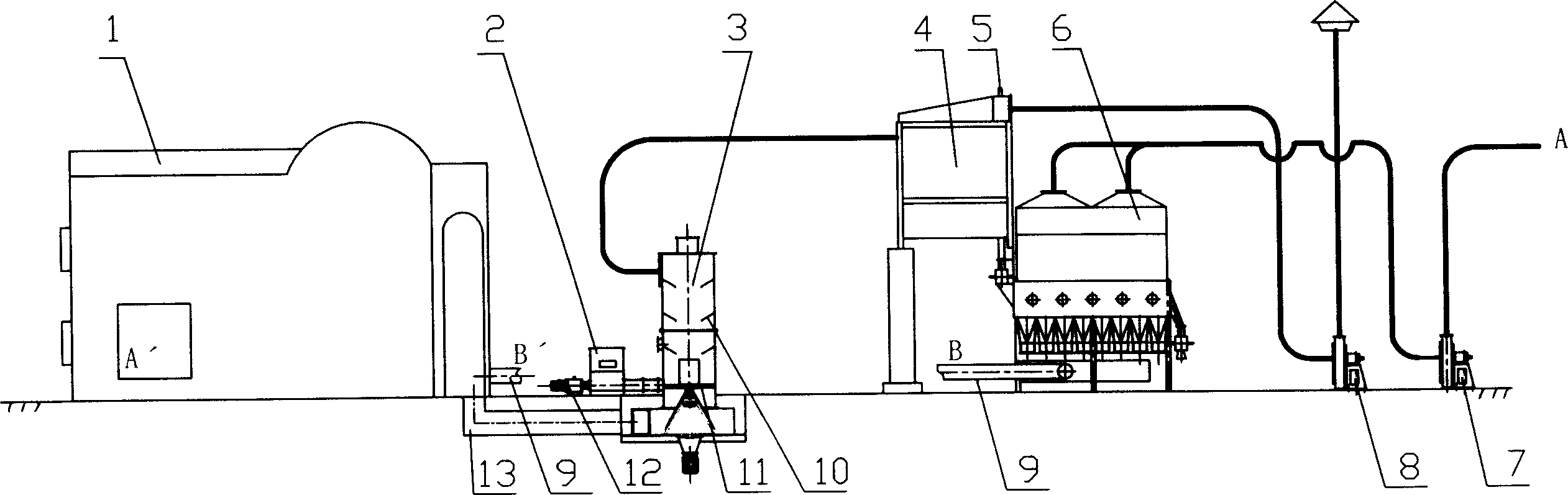
[0016] The drying method of the high-humidity material involved in the present invention is to quickly dry the high-humidity material in a rotary airflow dryer to reduce its moisture content to 25% to 35%, and then dry the material particles leaving the airflow dryer with the airflow. The gas is separated, and then the material enters the fluidized bed dryer to continue drying to reduce the moisture content to below 17%.

[0017] As shown in the accompanying drawings, the high-humidity material drying unit applying the above-mentioned drying method includes a hot blast stove 1, a rotary airflow dryer 3, a fluidized bed dryer 6 and a feeder 2 driven by a speed-regulating motor 12. It also includes Cyclone separator 4, induced draft fan 8 and blower 7. The air inlet of the rotary airflow dryer 3 is connected to the outlet of the flue gas pipe 13 of the hot blast stove, the outlet of the rotary airflow dryer 3 is connected to the inlet of the cyclone separator 4, and the outlet o...


PUM


Abstract

The present invention discloses a method for drying high-wet material. Said method includes the following two steps: firstly, quickly drying high-wet material in rotary pneumatic dryer to make its water content be reduced to 25-35%, then feeding the material into fluidized bed drying machine to continuously dry said material and make its water content be less than 17%. Its drying machine unit includes rotary pneumatic dryer and fluidized bed drying machine.

Description

technical field [0001] The invention belongs to the method of drying solid materials by heating, in particular relates to a method for drying high-humidity materials, and also relates to a drying unit applying the method. Background technique [0002] Many food, pharmaceutical, and chemical wastes, such as distiller's grains, fruit residues, and medicinal residues, are paste-like, pasty high-moisture and viscous materials, which bring many difficulties to drying. At present, the most commonly used machine is the rotary cylinder dryer. and rotary airflow quick dryer. [0003] The rotary cylinder dryer is a rotating cylinder slightly inclined to the horizontal line. The material enters from the higher end, and as the cylinder rotates, the material moves to the lower end under the action of gravity. The inner wall of the cylinder is equipped with lifting flight, which can lift the materials and scatter them, increases contact surface area of ​​materials and airflow, in order t...

Claims


Application Information

Patent Timeline
IPC IPC(8): F26B20/00F26B3/02
Inventor 王初阳
Owner 王初阳
Why Eureka
Try Eureka