Multiple angle cramping apparatus
A multi-angle, fixture technology, applied in the direction of clamping, manufacturing tools, workpiece clamping devices, etc., can solve problems such as high prices, achieve the effects of reducing processing costs, ingenious structural design, and significant technological progress
- Summary
- Abstract
- Description
- Claims
- Application Information
AI Technical Summary
Problems solved by technology
Method used
Image

Examples
Embodiment Construction
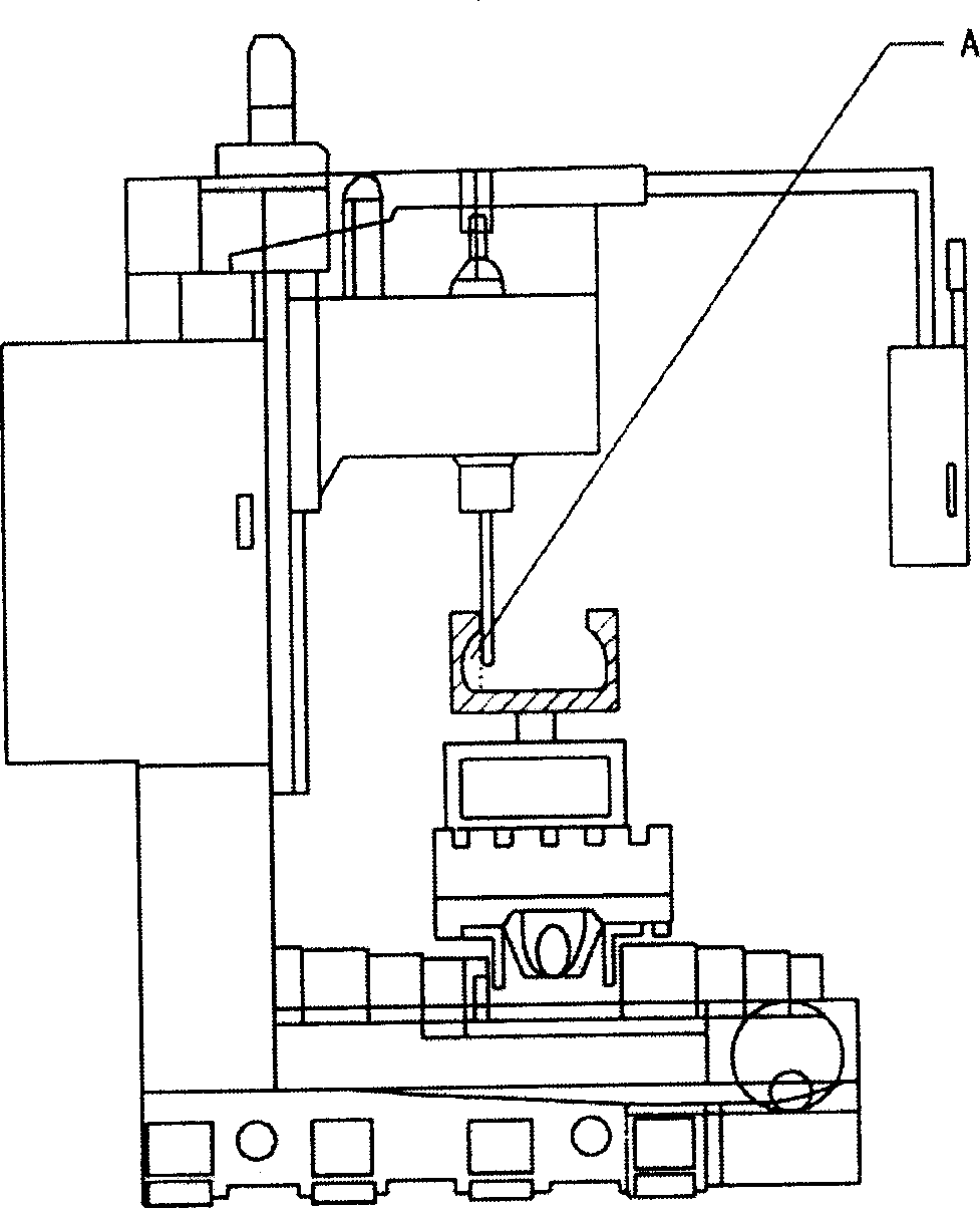
[0010] refer to figure 1 , the existing square fixture is processed on a three-axis CNC engraving and milling machine by clamping an inner circular workpiece with a small inner diameter above and a large bottom below through a fixed block. figure 1 It is difficult to process A in A, and there will be surplus material in A.
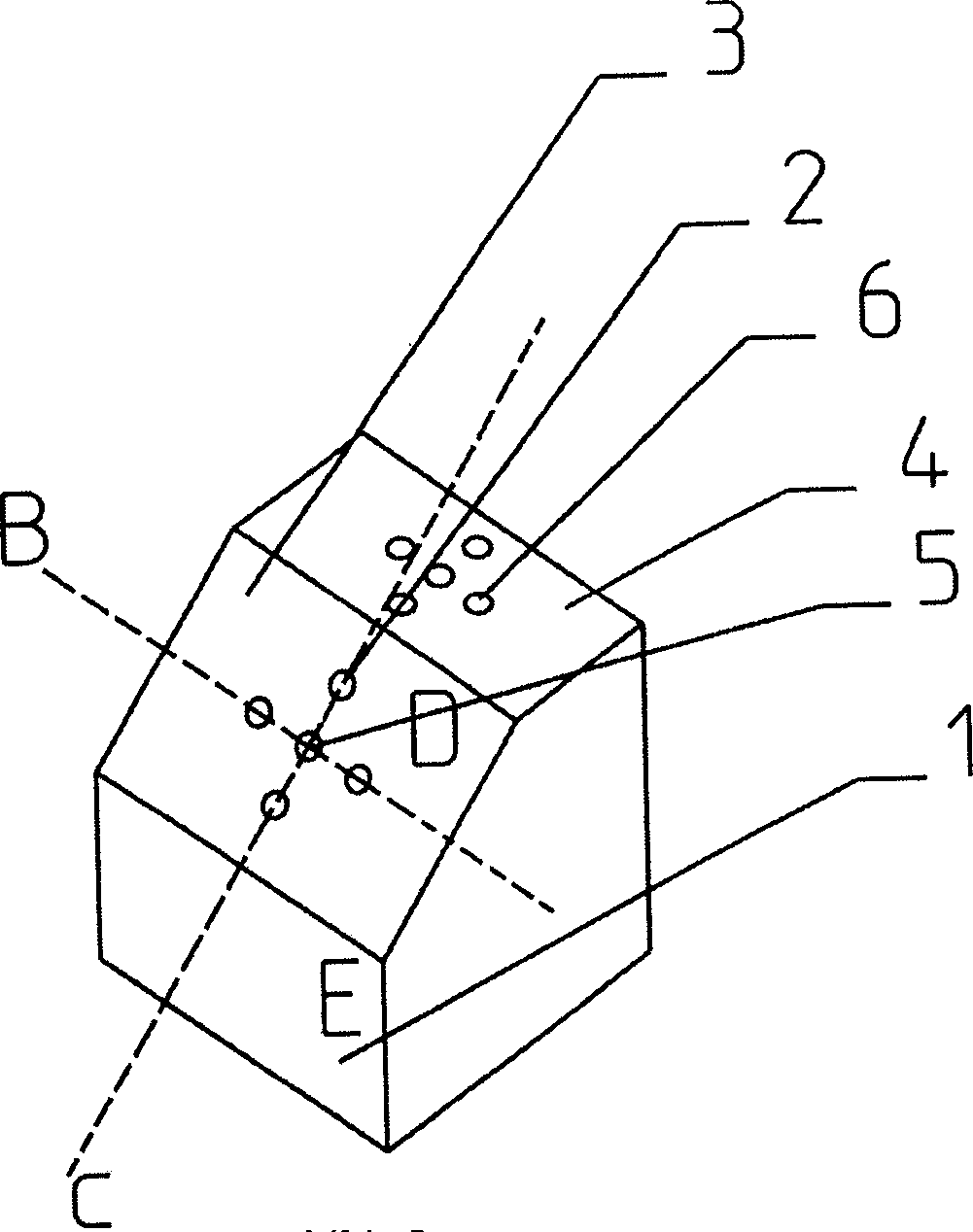
[0011] refer to figure 2 As can be seen, the multi-angle fixture of the present invention comprises side, bottom surface, top surface 4 (this top surface has been provided with a plurality of circular holes 6), and bottom surface and top surface become parallel state, and side surface and bottom surface are connected at right angles, and described one The intersection of the side surface 1 and the top surface 4 is an inclined surface 3 , and at least two workpiece fixing circular holes 2 are arranged in the middle of the inclined surface 3 . Wherein the upper line of the slope (i.e. the intersection line D) is connected to the top surface 4, and the low...
PUM
 Abstract
Description
Claims
Application Information
 - Generate Ideas
- Intellectual Property
- Life Sciences
- Materials
- Tech Scout
- Unparalleled Data Quality
- Higher Quality Content
- 60% Fewer Hallucinations
Browse by: Latest US Patents, China's latest patents, Technical Efficacy Thesaurus, Application Domain, Technology Topic, Popular Technical Reports.
© 2025 PatSnap. All rights reserved.Legal|Privacy policy|Modern Slavery Act Transparency Statement|Sitemap|About US| Contact US: help@patsnap.com