
Connector unit of steel frame and connection method

A joint device and connection method technology, which is applied in the field of support devices, can solve the problems of steel arch lateral stability, increased construction costs, poor assembly accuracy, etc., and achieve the effects of saving temporary processing components, convenient adjustment, and easy operation

Active Publication Date: 2006-09-27
CHONGQING BIAOWANG MACHINERY EQUIP CO LTD
View PDF0 Cites 4 Cited by
  • Summary
  • Abstract
  • Description
  • Claims
  • Application Information

AI Technical Summary

Problems solved by technology

In the construction of arch bridges, the steel arch frame is usually connected by pins in the prior art, which is more convenient, but there is generally a gap of about 0.1 to 0.5 mm between the pins and the pin holes, which makes the assembly accuracy relatively poor, and the steel arch frame Lateral stability also has a certain impact, so more wave and wind ropes must be added to maintain the stability of the arch bridge
For arch bridges with different spans, connecting plates or connecting rods of different specifications are often used in the prior art in order to adjust the arch spans and arcs. These processed parts will have slight differences due to differences in spans and heights. In different cast-in-place constructions It cannot be used universally, which increases the construction cost and causes great waste

Method used


Image

  • Connector unit of steel frame and connection method
  • Connector unit of steel frame and connection method
  • Connector unit of steel frame and connection method

Examples


Embodiment Construction

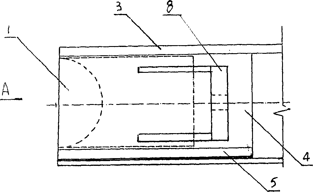
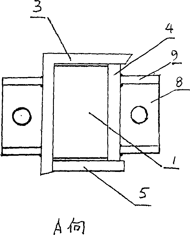
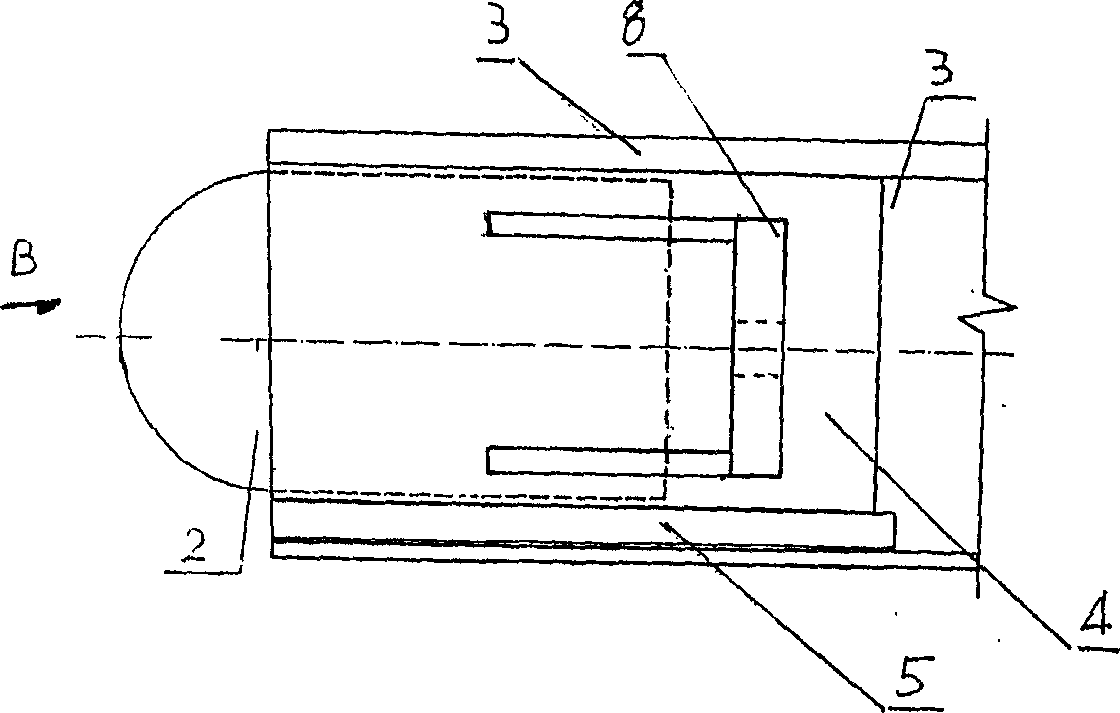
[0019] Such as figure 1 , figure 2 , image 3 , Figure 4 As shown, the female end arc head 1 or the male end arc head 2 is arranged in the joint end of the chord 3, and there are reinforced side plates 4 and reinforced bottom ribs 5 around it, and there are connecting anchor plates on the inside and outside of the joint end 8. Such as Figure 5 Image 6 As shown, the regulating tile 7 is tile-shaped, and its convex surface and concave surface are arc surfaces, and the concave surface of the female end arc head 1, the convex surface of the male end arc head 2, and the convex and concave surfaces of the adjusting tile 7 are circular. The arc diameters are the same. Such as Figure 7 As shown, the chord 3 at one end of the joint is provided with a female-end circular arc head 1, and there is a connecting anchor plate 8 on the outside of it. The male end circular arc head 2 also has a connecting anchor plate 8 and an anchor plate reinforcement rib 9 on its outer side. C...


PUM


Abstract

The invention relates to a connector of steel support, which comprises: a connector and an adjusting tile. Wherein, one end of connector has a positive arc head (2) whose outer side is connected to the anchor plate (8), and another head has a passive arc head (1) whose outer side is connected to the anchor plate (8); the concave and convex surfaces of adjusting tile are both arc surface, while the positive arc head (2) is the convex surface and the passive arc head (1) is the concave surface, with the same diameter. The method comprises: inserting the positive arc head (2) into the passive one, which are connected by using connecting bolt through the anchor plate (8). And by adding adjusting tile (7) between positive arc head (2) and passive arc heads (1), the adjustment can be realized. The invention has simple operation and adjustable longitudinal arc without displacement.

Description

technical field [0001] The invention relates to a support device for civil construction, in particular to a joint device and connection method for a steel frame structure used for arch bridge construction. Background technique [0002] The joint device connecting the steel frame and the steel frame is a structure often used in engineering, such as the connection of each segment of the bridge arch support, the connection of the longitudinal beam support of the bridge erecting machine, the connection of the gantry, the connection of the frame construction platform, etc. . In the construction of arch bridges, the steel arch frame is usually connected by pins in the prior art, which is more convenient, but there is generally a gap of about 0.1 to 0.5 mm between the pins and the pin holes, which makes the assembly accuracy relatively poor, and the steel arch frame Lateral stability also has a certain influence, and more wave and wind ropes must be added to maintain the stability...

Claims


Application Information

Patent Timeline
Patent Type & Authority Applications(China)
IPC IPC(8): E01D21/00E01D4/00
Inventor 何开智张有德
Owner CHONGQING BIAOWANG MACHINERY EQUIP CO LTD
Learn More