Robot controlling device

A control device, robot technology, applied in the direction of digital control, program control, electrical program control, etc., can solve the problems of movement speed change, contact and so on

Inactive Publication Date: 2006-09-27
MITSUBISHI ELECTRIC CORP
View PDF1 Cites 17 Cited by
  • Summary
  • Abstract
  • Description
  • Claims
  • Application Information

AI Technical Summary

Problems solved by technology

[0005] However, the robot control device configured as above has a problem in that the operator must monitor the arm while the arm is released, because the moving speed changes rapidly when the brake is released depending on the weight, posture, and load conditions of the arm. Adjust the setting of the lock and release time of the brake while moving
[0006] In addition, there is a problem that, while the servo control unit is stopped, the working point of the arm or the like may come into contact with the stopper, the robot main body, peripheral equipment, etc.

Method used


Image

  • Robot controlling device
  • Robot controlling device
  • Robot controlling device

Examples


Embodiment 1

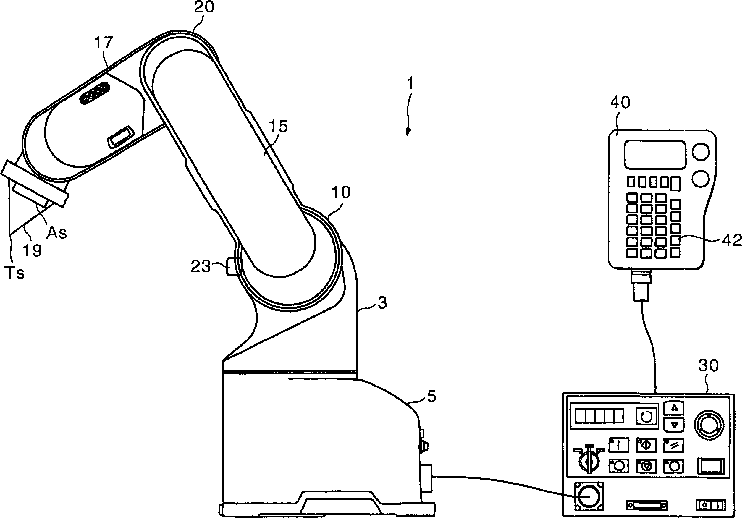
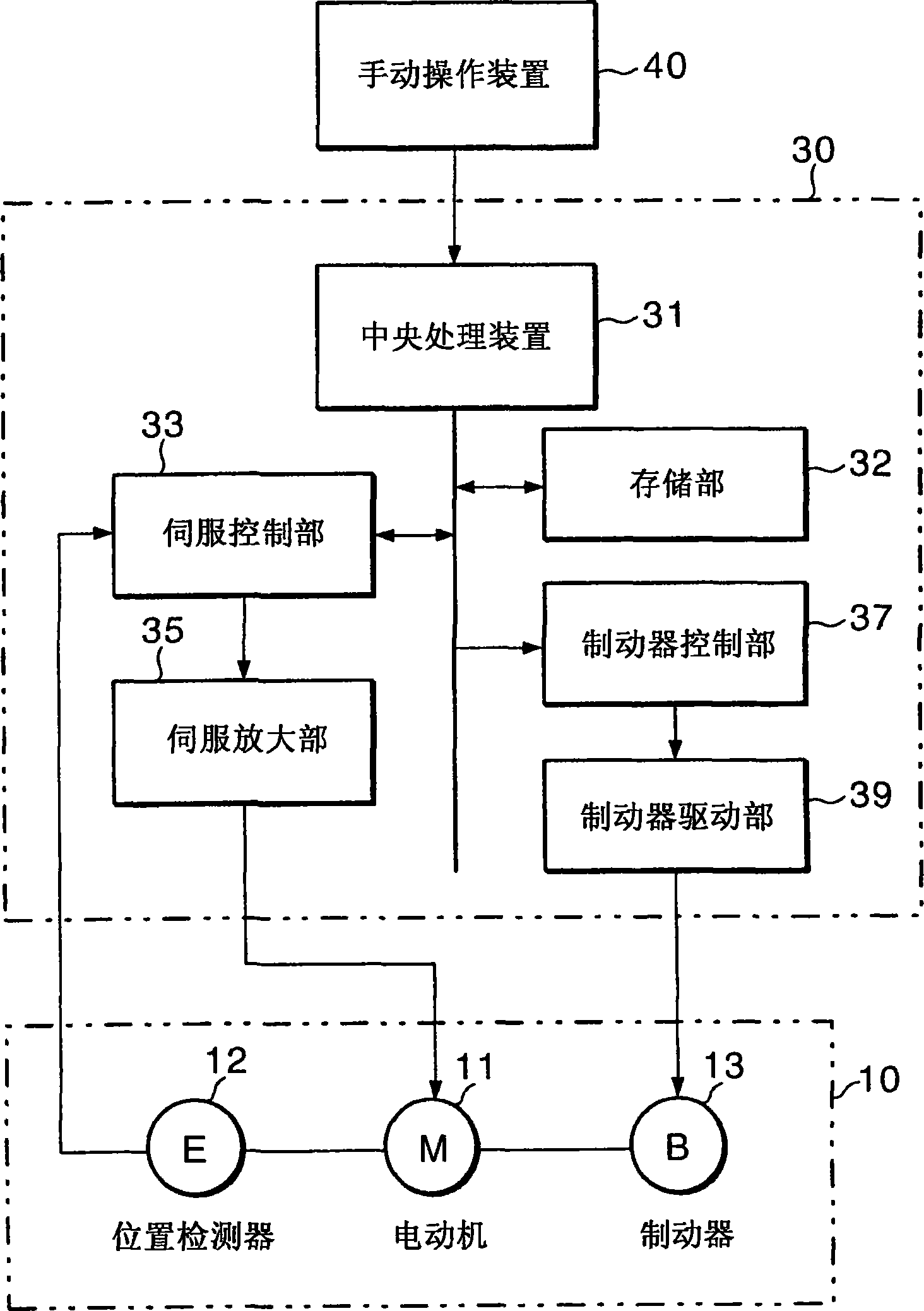
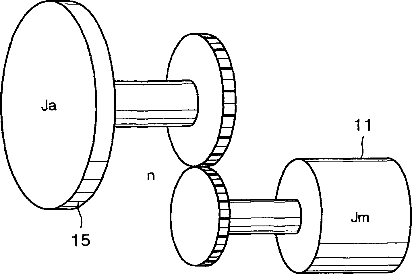
[0032] according to Figure 1 to Figure 4 One embodiment of the present invention will be described. figure 1 is an overall configuration diagram of a robot system representing an embodiment, figure 2 yes means figure 1 A block diagram of the electrical system of the robotic system is shown, image 3 is a model diagram of a joint consisting of an arm and a motor, Figure 4 is the correspondence between the load torque and the angle of the arm.

[0033] exist figure 1 Among them, the robot system 1 has: a control device 30 that has a servo control unit 33 that controls the robot 3, and has a teaching function as a position recognition unit for teaching the end Ts (working point) of the robot 3; The operation device 40 executes the operation of the robot 3 and also has a release operation switch 43 as a command unit for turning the servo control unit 33 on and off.

[0034] The robot 3 has: a main body 5, which is set upright; a first arm 15, which is connected to the mai...

Embodiment 2

[0062] In the above-mentioned embodiment, the duty cycle of switching on and off of the brake 13 is changed according to the angle difference between the arm 15 and the stopper 17. The following description also considers the speed of the arm 15 to make the switching on and off of the brake 13 Example of duty cycle variation.

[0063] Formula (3) above is reformulated as follows.

[0064] ω=dθ / dt=[(TL-Tb) / J 0 〕t

[0065] Integrating both sides of this formula becomes the following formula.

[0066] θ=(TL-Tb)t 2 / (2J 0 )+B……(7)

[0067] Since θ=0 at t=0, the integral constant B=0.

[0068] θ=(TL-Tb)t 2 / (2J 0 ) ……(8)

[0069] In the above formula (8), assuming that the load torque TL is a constant value regardless of the angle difference, when the arm 15 exceeds the maximum rotation speed ωmax, the deceleration of the arm 15 is made constant by the restraint brake 13 . Because the deceleration is constant, the deceleration time is proportional to the angle differen...

Embodiment 3

[0076] The first embodiment described above is provided with a stopper 23 that limits the rotation of the arm 15. In this embodiment, in the robot 3 that can contact the main body 5 and the end As of the second arm 17 as the work point, the arm 17 is prevented from being rotated. The control of the stopper 13 in which the end As is in contact with the main body 5 will be described.

[0077] The robot system of the present embodiment and figure 1 The same as shown, including the second joint part 20 and constituted as follows Figure 9 electrical system shown. Figure 9 in, with figure 2 The same reference numerals denote the same parts, and explanations thereof are omitted. exist figure 1 and Figure 9 Among them, the robot 3 has two joints 10, 20, the first joint 10 is driven by the first motor 11, and the second joint 20 has: the second motor 111, which drives the arm 17; the second position as the second position detection unit A detector 112 detects the rotational p...


PUM


Abstract

It comprises a rotatable arm (15), a motor (11) for driving the arm (15), a position detector (12) for detecting the angular position of the motor (11) to generate a position detection signal, a stop (23) for controlling the rotation of the arm (15), a brake (13) for restraining and releasing the rotation of the motor (11), a servo control section (33) for driving the motor (11), and a cancellation operating switch (42) for disabling the servo control section (33) and releasing the brake (13), and a brake control section (37) for changing the time for restraining or releasing the brake (13) according to the angle between the stop (23) and the arm (15) by the actuation of the cancellation operating switch (42).

Description

technical field [0001] The present invention relates to the method of keeping the arm of the robot from touching the stopper, etc. during maintenance, etc. [0002] Improvements in technology. Background technique [0003] A conventional robot control device will be described based on Japanese Patent Application Laid-Open No. 11-179691. According to this publication, a robot control device is described, which controls the position of the arm of the robot by the operation of the servo control unit, and has a brake that brakes the arm when the servo control unit is not in operation. The control device of the robot has a brake The brake control unit has a lock time setting unit for locking the brake for a predetermined time, and a release time setting unit for releasing the brake for a predetermined time, and when there is a brake release command from the operation unit, the lock time setting The setting time of the fixing part and the release time setting part alternately lo...

Claims


Application Information

Patent Timeline
Patent Type & Authority Applications(China)
IPC IPC(8): B25J19/00G05B19/19B25J9/16B25J13/06
CPCG05B2219/40218G05B19/19B25J19/0004B25J9/1674
Inventor 高桥浩喜北村笃史水谷朋治
Owner MITSUBISHI ELECTRIC CORP
Why Eureka
Try Eureka