
Luminescent assembly LED cluster lamp spot beam control system

A technology of light-emitting components and control systems, which can be applied to instruments, static indicators, etc., and can solve the problems of not being able to simultaneously control decorative LED tubes and display dynamically at the same time

Inactive Publication Date: 2006-10-04
OWNWAY TECH
View PDF0 Cites 4 Cited by
  • Summary
  • Abstract
  • Description
  • Claims
  • Application Information

AI Technical Summary

Problems solved by technology

Although the digital lighting controller DMX512 has been developed, it can control, store, integrate and cooperate with dimmers to create rich and different display effects, but it is limited to a regional display and cannot control multiple buildings or buildings at the same time Decorative Light-Emitting Diode Tubes (LEDs) display dynamically at the same time

Method used


Image

  • Luminescent assembly LED cluster lamp spot beam control system
  • Luminescent assembly LED cluster lamp spot beam control system
  • Luminescent assembly LED cluster lamp spot beam control system

Examples


Embodiment Construction

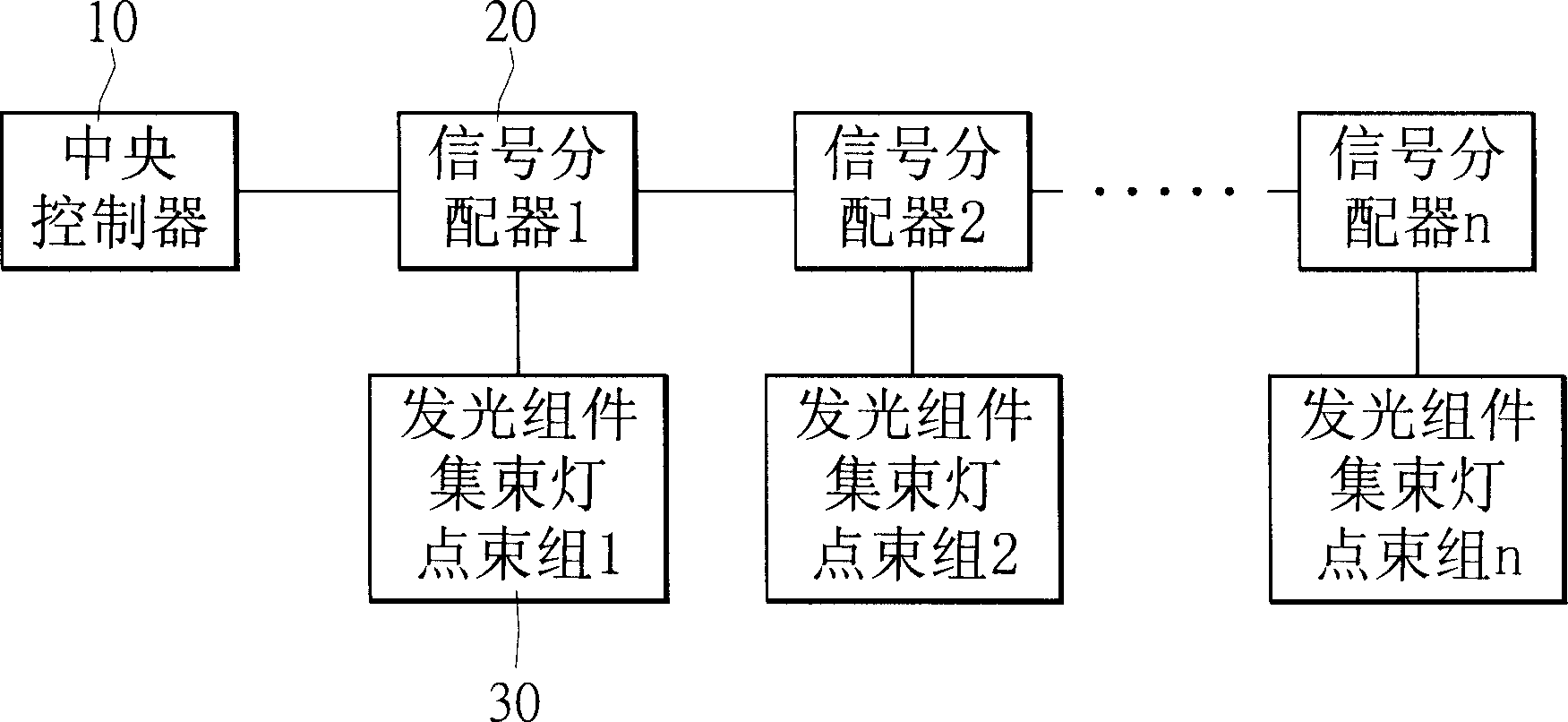
[0036] Please refer to figure 1 , which is a schematic diagram of the structure of the light-emitting assembly cluster lamp lighting control system of the present invention. The system of the present invention controls single or several signal distributors 20 by a central controller 10, and transfers at least one video data output by the central controller 10 to each light-emitting assembly cluster light spot composed of a plurality of light-emitting assembly cluster light points. Group 30 (ie display unit). Therefore, the feature of the present invention is the function of controlling multiple objects, that is, a central controller 10 can be used to control the display of multiple groups of display unit patterns through software editing.

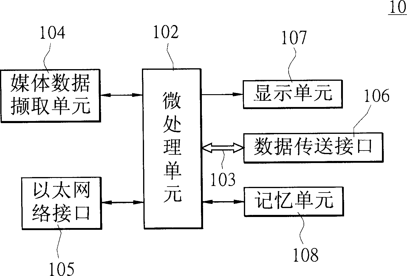
[0037] Cooperate figure 1 , please refer to figure 2 , which is a schematic block diagram of the internal circuit of the central controller of the present invention. The central controller 10 includes: a micro-processing unit 102 conne...


PUM


Abstract

The driver for cluster lamp spot comprises: processing edited video or multimedia with a CPU serial connected with multiple signal distributors, and outputting different video data to the luminous body combined by cluster spots to show corresponding design.

Description

technical field [0001] The present invention relates to a light-emitting assembly cluster light lighting control system, which can transmit different video data to each light-emitting assembly light beam lighting group, so that they respectively present an image corresponding to the video data. Background technique [0002] The discovery of electricity and the invention of lighting have made lighting no longer limited to natural light sources. Coupled with the development of the electronics industry, the lighting method using electricity as a light source has become controllable. Therefore, the industry has made extensive use of it. In addition to night lighting, decorative lighting with visual characteristics has also been developed, such as neon lights, laser lights, LEDs, etc., and the biggest feature of these decorative lighting is that it can be patterned. In addition, lighting tubes are arranged around the perimeter of the building, so that the outline of the building ...

Claims


Application Information

Patent Timeline
Patent Type & Authority Applications(China)
IPC IPC(8): G09G3/14G09G3/32
Inventor 余德政孙尚哲赖治维邱皇达林万枝廖皓帆徐明珠
Owner OWNWAY TECH
Learn More