
Substrate feed chamber and substrate processing apparatus

A substrate processing device and substrate conveying technology, which is used in thin material processing, conveyor objects, transportation and packaging, etc., can solve the problems of increasing the occupied area of ​​the device, worsening the efficiency of feeding and feeding, and increasing the processing capacity. and other problems, to achieve the effect of suppressing deflection and preventing unevenness

Inactive Publication Date: 2006-10-04
CANON ANELVA CORP
View PDF2 Cites 5 Cited by
  • Summary
  • Abstract
  • Description
  • Claims
  • Application Information

AI Technical Summary

Problems solved by technology

When this configuration is adopted, the occupied area of ​​the device can be further increased, and it is not preferable from the viewpoint of increasing the throughput.
[0014] In addition, in the substrate processing apparatus disclosed in Document 2, the restriction on the number of substrates when storing substrates stored in other processing chambers in the buffer chamber degrades the efficiency of loading and unloading operations, and cannot improve the throughput.

Method used


Image

  • Substrate feed chamber and substrate processing apparatus
  • Substrate feed chamber and substrate processing apparatus
  • Substrate feed chamber and substrate processing apparatus

Examples


Embodiment Construction

[0052] Embodiments of the present invention will be described below with reference to the drawings. Each drawing is merely a schematic illustration of the size and arrangement relationship of each component to the extent that the present invention can be understood, and therefore, the present invention is not limited to the examples in the drawings. In addition, in each drawing for explanation, the same components are denoted by the same symbols, and their repeated description may be omitted.

[0053] (first embodiment)

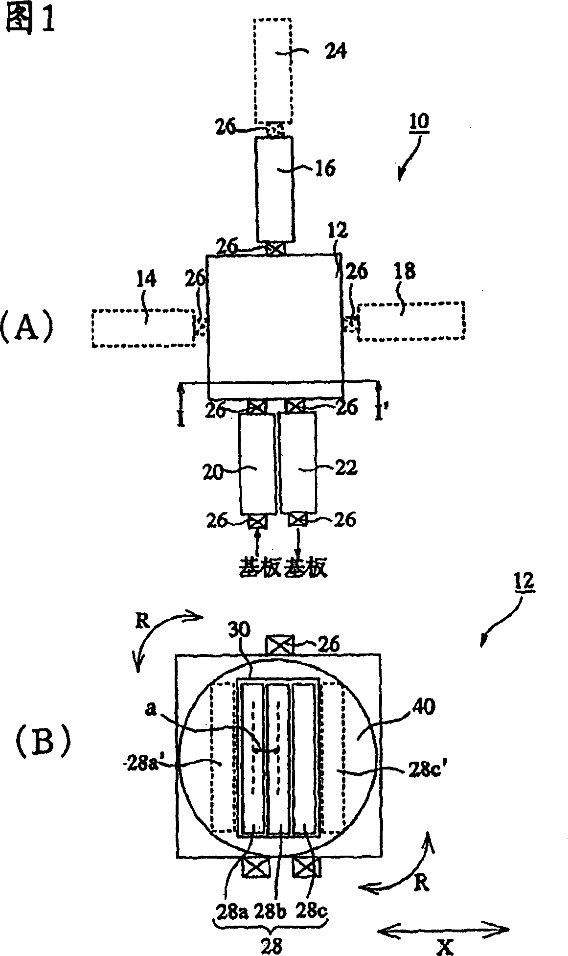
[0054] 1(A) and (B) are diagrams schematically showing a configuration example of a first substrate processing apparatus 10 of the present invention. 1(A) is a schematic plan view of a first substrate processing apparatus 10, and FIG. 1(B) is a schematic plan view for explaining the substrate transfer chamber 12 of FIG. 1(A).

[0055] 1. Description of the substrate processing apparatus of the present invention

[0056] As shown in FIG. 1(A), the first sub...


PUM


Abstract

A substrate feed chamber that is equipped in a substrate processing apparatus is provided. The substrate feed chamber has a storage tray capable of storing simultaneously three or more substrate holding trays that hold substrates in a vertical or substantially vertical condition and a horizontal movement mechanism that moves horizontally the storage tray with respect to the substrate feed position in order to effect feeding-in or feeding-out movement of the substrate holding tray between any of the chambers of a group consisting of processing chambers and load lock chambers and, in addition, if required, has a rotary movement device that rotates the storage tray. Improvement in throughput in a substrate processing apparatus can thereby be achieved and increase in the ground-contacting area of the device as a whole can be prevented.

Description

[0001] The patent application of the present invention is a divisional application of the patent application with the filing date of September 24, 2002, the application number of 02132338.0, and the title of the invention of "substrate conveying chamber and substrate processing device". technical field [0002] The present invention relates to a substrate transfer chamber and a substrate processing device suitable for manufacturing display devices such as liquid crystal displays. Background technique [0003] In the manufacture of various display devices such as liquid crystal displays, a substrate processing device (vacuum processing device) for performing surface treatment on a substrate is generally mainly composed of a load airtight chamber, a processing chamber, and a transfer chamber. Substrates are carried in and out between atmospheres, and the processing chamber performs predetermined film formation processing, etching, heating or cooling heat treatment on the substr...

Claims


Application Information

Patent Timeline
Patent Type & Authority Applications(China)
IPC IPC(8): H01L21/677G02F1/1333G02F1/13B65G49/00B65G49/06
CPCH01L21/67742H01L21/67745Y10S414/135G02F1/13
Inventor 高桥信行
Owner CANON ANELVA CORP
Features
  • Generate Ideas
  • Intellectual Property
  • Life Sciences
  • Materials
  • Tech Scout
  • Unparalleled Data Quality
  • Higher Quality Content
  • 60% Fewer Hallucinations
Learn More