
Switched reluctance generator with improved generation efficiency in low-speed range

A switched reluctance and generator technology, which can be applied to control generators, control generators, and AC motors through magnetic field changes.

Inactive Publication Date: 2006-10-04
LG ELECTRONICS INC
View PDF0 Cites 2 Cited by
  • Summary
  • Abstract
  • Description
  • Claims
  • Application Information

AI Technical Summary

Problems solved by technology

The induction generator is simple in structure and cheap in cost, but its disadvantage is that it needs an additional gearbox to maintain a stable speed when generating electricity, and the wind speed range necessary for electricity generation is limited
The disadvantage of synchronous generators is that the structure is complex and expensive
In addition, in the synchronous generator, when the wind speed is low, the battery pack is not charged because the output voltage from the generator is small.
Therefore, in low wind speed areas such as South Korea, it is very difficult to generate electricity using induction generators or synchronous generators

Method used


Image

  • Switched reluctance generator with improved generation efficiency in low-speed range
  • Switched reluctance generator with improved generation efficiency in low-speed range
  • Switched reluctance generator with improved generation efficiency in low-speed range

Examples


Embodiment Construction

[0017] Exemplary embodiments according to the present invention will now be described in detail with reference to the accompanying drawings.

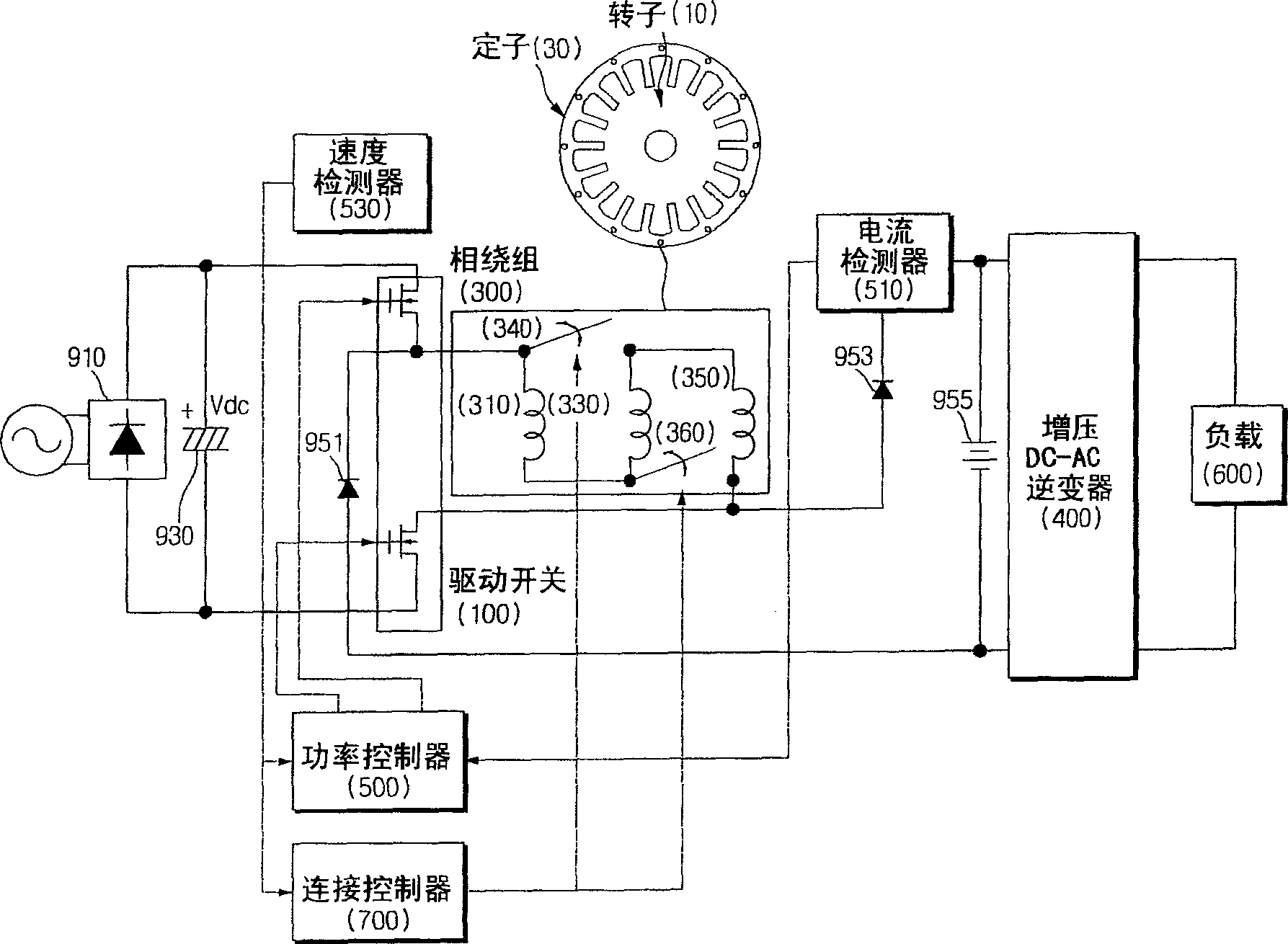
[0018] figure 1 is a block diagram showing the configuration of the SR generator according to the embodiment of the present invention. Such as figure 1 As shown in , the SR generator includes: a rotor 10; a stator 30, on which a phase winding (phase winding) is wound; a drive switch 100, which controls the current flow in the phase winding 300; and a power controller 500, which controls the drive switch 100's of toggles. The SR generator is configured such that the inductance of the phase winding 300 becomes larger in the low speed range and smaller in the high speed range.

[0019] The SR generator according to the embodiment of the present invention further includes: a phase winding 300, which has a plurality of unit windings (unit windings) 310, 330, 350 and at least one winding switch 340 for connecting or disconnecting the unit ...


PUM


Abstract

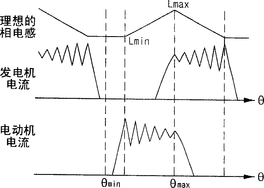
Disclosed is an SR (switched reluctance) generator with improved generation capability in a low-speed range. The SR generator is configured such that an inductance of a phase winding wound around a stator is increased in a low-speed range and is reduced in a high-speed range. Accordingly, a variation rate of the inductance relative to a phase angle is increased in a low-speed range, resulting in an increased output energy in a low-speed range and an improved generation efficiency. The phase winding of the stator may be configured to have a single phase. Accordingly, since the generator is configured with the reduced number of switches, it can be manufactured inexpensively and simply.

Description

[0001] This application claims priority from Korean Patent Application No. 2005-0027620 filed on Apr. 1, 2005, the entire disclosure of which is hereby incorporated by reference into this application. technical field [0002] The present invention relates to a switched reluctance (SR) generator, and more particularly to an SR generator having improved power generation performance in the low speed range. Background technique [0003] An SR generator is an energy conversion device that applies electrical energy through electronic switching from a voltage source to a winding having at least one phase within a specified range of rotor angles, withdrawn from a phase winding of a subsequent range of rotor angles The energy is greater than the previously applied energy. This additional energy is mechanical and is transferred to the generator rotor by applying a torque in the direction of rotation. The advantage of this SR generator is that it can generate power in the low speed ra...

Claims


Application Information

Patent Timeline
Patent Type & Authority Applications(China)
IPC IPC(8): H02P9/14H02P9/00H02K11/00
CPCH02P25/085H02P25/08H02P25/092H02P9/48H02P9/14
Inventor 林俊荣崔镛远
Owner LG ELECTRONICS INC
Learn More