
Ruggedized two-axis optical beam steering device

a two-axis, optical beam technology, applied in the direction of optics, mountings, instruments, etc., can solve the problems of insufficient space and access in many directions, limited space available for optical mounts and easy access thereto, and many prior art optical mounts that are not designed to operate within or survive the harsh environment normally encountered

Active Publication Date: 2014-03-06
ROSEMOUNT AEROSPACE
View PDF0 Cites 2 Cited by
  • Summary
  • Abstract
  • Description
  • Claims
  • Application Information

AI Technical Summary

Benefits of technology

The invention is a device that allows for the adjustment of an optical beam's position in two different directions. The device includes a gimbal and a roll cage, which can rotate and tilt to direct the beam. The device also includes external adjusting means that allow for the independent adjustment of the gimbal and roll cage, which helps to eliminate cross-coupling issues. Overall, this invention simplifies the process of manufacturing and assembly while improving the accuracy of optical beam steering.

Problems solved by technology

Thus, a significant amount of space and access in many directions is required to make adjustments to the beam steering components.
These spatial issues become most problematic when the optical mount is employed in applications such as aircraft that employ optical guidance, navigation, control, tracking systems, air data sensing, ice detection, water droplet size sensing, water content sensing and imaging, where the amount of space that is available to house the optical mount and ready access thereto is extremely limited.
Furthermore, many prior art off-the-shelf optical mounts are not designed to operate within or survive the harsh environments normally encountered in military applications involving aircraft and laser guided munitions.
Indeed, they often use light springs to hold components together, and can even require significant potting or epoxy for locking the components in place to prevent them from moving once adjusted.
This creates cross-coupling in at least one of the axes (i.e., one adjustment changes the angle of the mount around two axes), which is a disadvantage.
In addition, the mechanism for locking the optical steering components on certain prior art optical mounts can alter or disrupt a previously adjusted set position of the optical component.

Method used


Image

  • Ruggedized two-axis optical beam steering device
  • Ruggedized two-axis optical beam steering device
  • Ruggedized two-axis optical beam steering device

Examples


Embodiment Construction

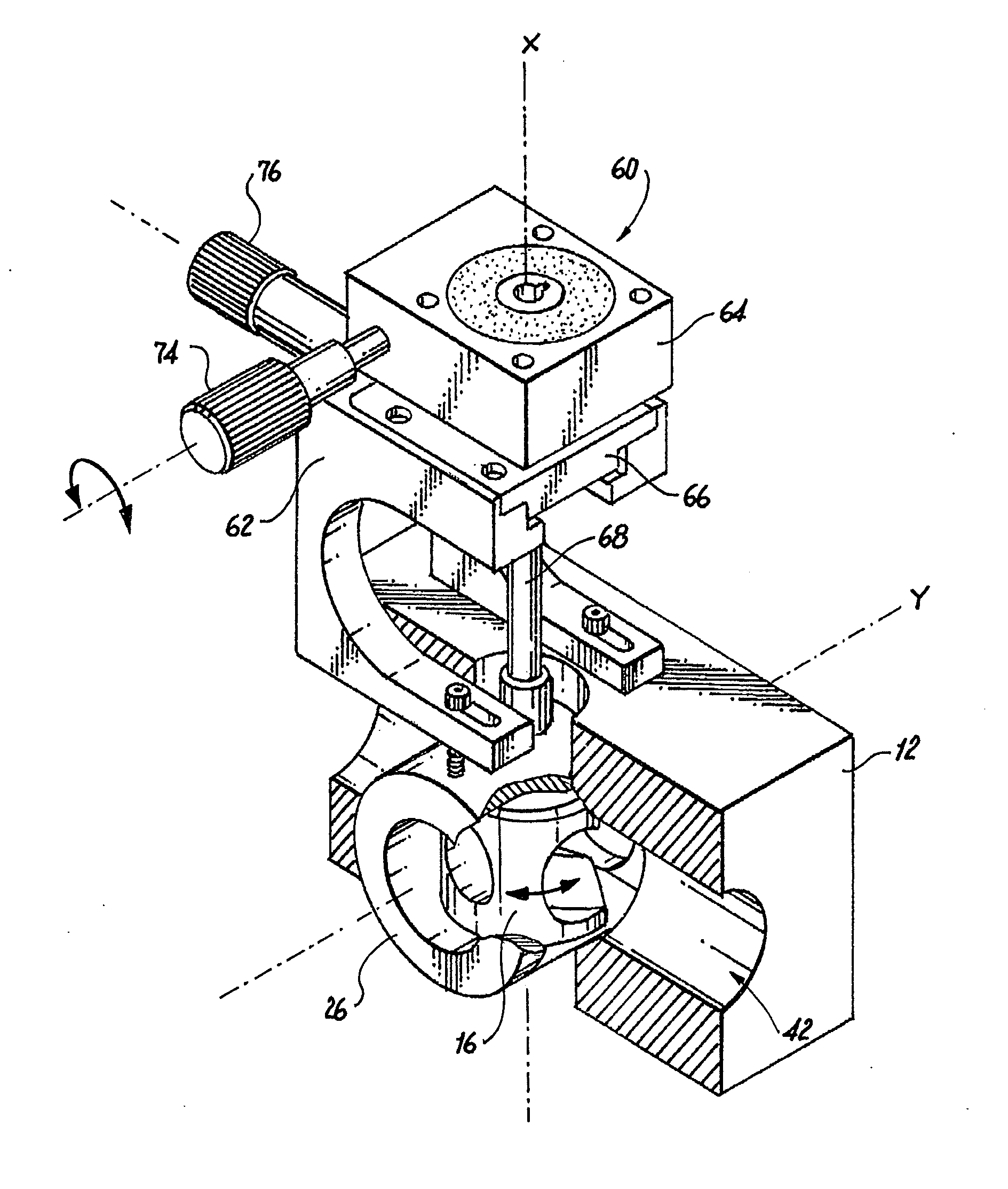
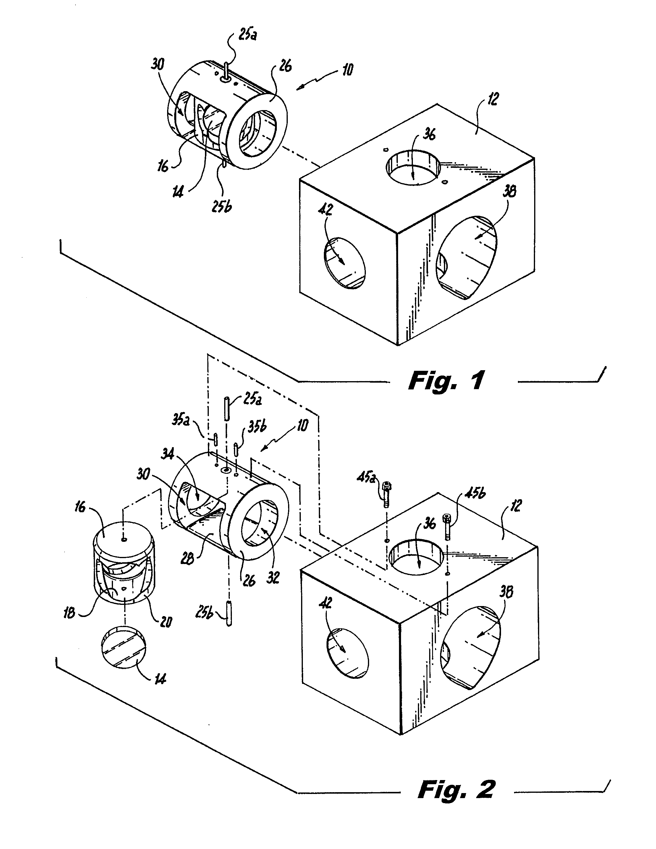
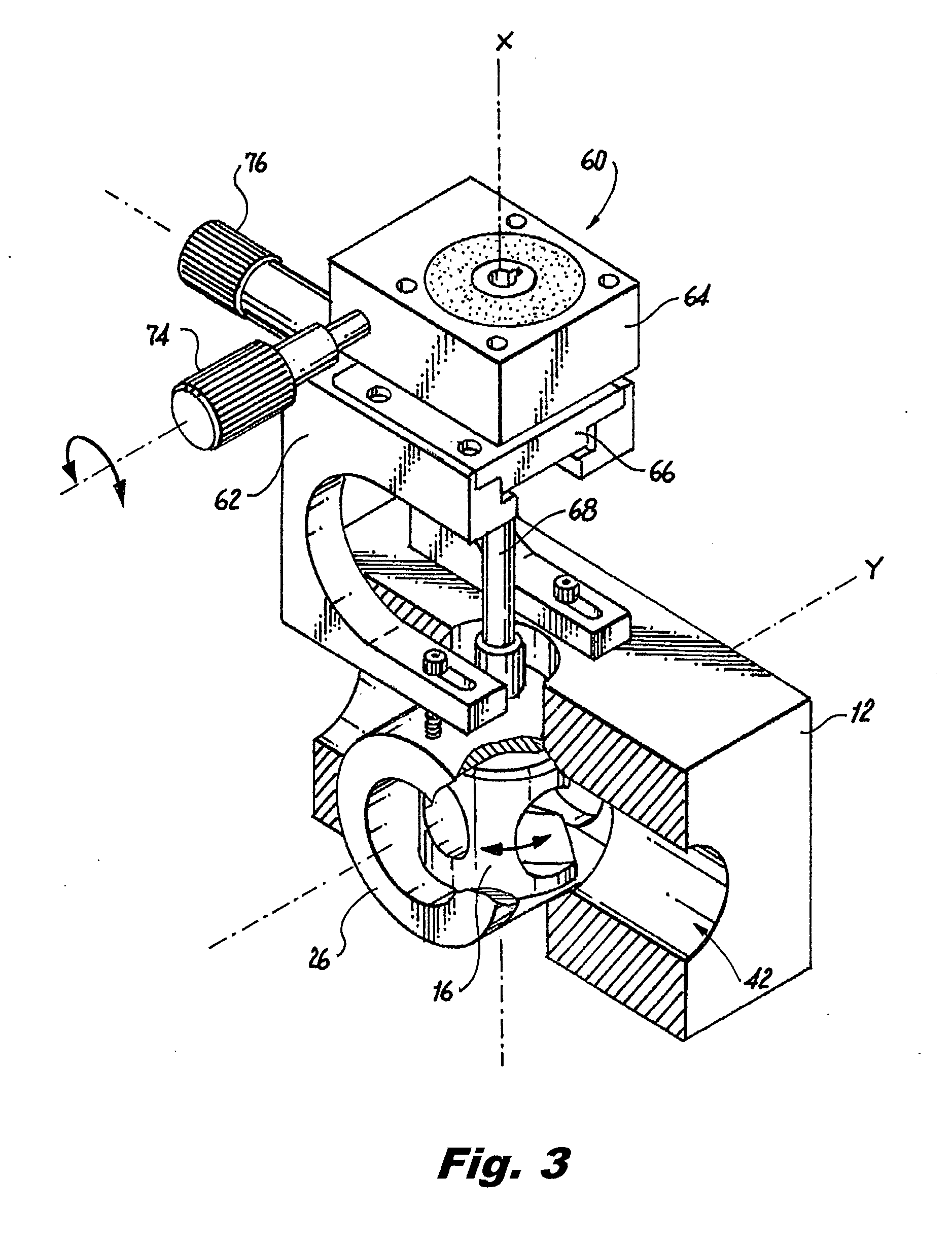
[0043]Referring now to the drawings wherein like reference numerals indentify similar structural features or elements of the preferred embodiments disclosed herein, there is illustrated in FIG. 1 a ruggedized two-axis optical beam steering device constructed in accordance with a preferred embodiment of the subject invention and designated generally by reference numeral 10.

[0044]For ease of illustration, the optical beam steering device 10 is shown in conjunction with a generic version of a mounting structure 12 configured to operatively support or otherwise mount the beam steering device 10. It should be readily appreciated by those having ordinary skill in the art that an actual mounting structure or mount for the beam steering device 10 would likely form part of a product body in an aircraft, missile or projectile, and would therefore conform with the system or componentry in which it is employed, for example, within a sensor body.

[0045]Referring to FIG. 2, the optical steering de...


PUM


Abstract

An optical beam steering device is disclosed which includes a compartment for containing an optical component for interacting with an optical beam, a gimbal supporting the optical component and defining a pan axis, a roll cage rotatably supporting the gimbal and defining a tilt axis, wherein the tilt axis is orthogonal to the pan axis, and a mount that houses and rotatably supports the roll cage, wherein the angular position of the roll cage with respect to the mount and the angular position of the gimbal with respect to the roll cage are both locked from one side of the mount.

Description

BACKGROUND OF THE INVENTION[0001]1. Field of the Invention[0002]The subject invention is directed to mounts for positioning optics in a desired orientation, and more particularly, to a ruggedized two-axis optical beam steering device for use in military, commercial and / or laboratory applications.[0003]2. Description of Related Art[0004]Gimbaled optical mounts for steering laser beams are well known in the art, as disclosed for example in U.S. Pat. No. 4,854,687 to Fletcher. Many commercially available off-the-shelf optical mounts are designed for bench top use and provide direct access to the mechanisms for making precision adjustments to the position of the optical component associated therewith. Thus, a system that employs off-the-shelf optical mounts will either have those mounts located in the open or the system will be designed to allow ready access to each mount, which may require a system designer to provide a relatively substantial amount of space for each mount.[0005]Most b...

Claims


Application Information

Patent Timeline
Patent Type & Authority Applications(United States)
IPC IPC(8): G02B26/08
CPCG02B7/004G02B7/023G02B7/1824G02B26/0816G02B27/1073
Inventor DEANGELO, TIMOTHY J.
Owner ROSEMOUNT AEROSPACE
Learn More