Measuring device for electrically measuring a flat measurement structure that can be contacted on one side

A measurement device and electrical measurement technology, which is applied in the field of measurement structure, can solve the problems of measurement result distortion, time-consuming, distortion, etc., and achieve the effect of speeding up the connection speed

Active Publication Date: 2015-03-04
FRAUNHOFER GESELLSCHAFT ZUR FOERDERUNG DER ANGEWANDTEN FORSCHUNG EV
View PDF7 Cites 0 Cited by
  • Summary
  • Abstract
  • Description
  • Claims
  • Application Information

AI Technical Summary

Problems solved by technology

Especially when the measuring structure is arranged on the side opposite the measuring surface for emitting or converting electromagnetic radiation, the following problems arise: On the one hand, the measuring surface is to be connected; On the one hand, the penetration of electromagnetic radiation should be only minimally affected during the measurement or calibration process, because during the measurement or calibration process, the measurement structure needs to be loaded with electromagnetic radiation and / or it should be measured during the measurement process. electromagnetic radiation emitted
[0004] The disadvantage of this measuring device is that, on the one hand, the solar cells are laid flat on the carrier element and pressed together with the aid of a glass plate, which constitutes a complex process which requires, in particular when measuring several solar cells in a production line time consuming
On the other hand, the glass plates used have absorption and reflection properties which distort the measurement results or which must be calibrated accordingly in order to be taken into account in the measurement results
In addition, the glass plate can become contaminated or damaged during use, causing additional distortion during the measurement

Method used


Image

  • Measuring device for electrically measuring a flat measurement structure that can be contacted on one side
  • Measuring device for electrically measuring a flat measurement structure that can be contacted on one side
  • Measuring device for electrically measuring a flat measurement structure that can be contacted on one side

Examples


Embodiment Construction

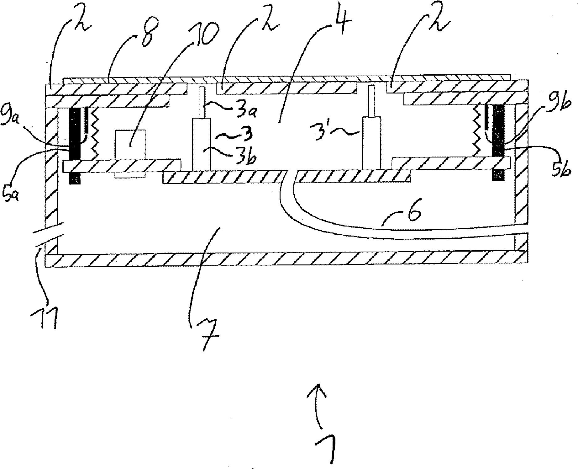
[0068] figure 1 A sectional view of an exemplary embodiment of the measuring device 1 according to the invention is shown, the sectional view extending perpendicularly to the carrier element 2 . The carrier element 2 is designed in one piece and has two recesses, figure 1 The sectional view shown in extends through the gap.

[0069] The measuring device has a plurality of switch-on units 3, in figure 1 Two of them (3, 3') are shown in the cross-section shown. The switch-on unit 3 is designed as a spring contact pin with pin 3a, figure 1 The pin in is supported in the cylindrical housing 3b so as to be movable upwards and downwards. The pin 3 a is spring-loaded, so that in the unloaded state the pin moves upwards.

[0070] The switch-on unit 3 is arranged on the bottom element of the first vacuum chamber 4 . The vacuum chamber is delimited upwards by the support element 2 and downwards by said bottom element. The vacuum chamber is sealed laterally by bellows-shaped eleme...


PUM


Abstract

A measuring device for electrically measuring a measurement structure that can be electrically contacted at one measuring side, in particular an optoelectronic element, such as a solar cell, including at least two contacting units for electrically contacting the measurement structure and at least one support element for supporting the measurement structure with the measuring side on the support element. It is essential that the measuring device includes at least one suction line for the connection to the suction unit and at least one suction opening that is connected in a fluid-conducting manner to the suction line, wherein the suction opening is arranged in and / or on the support element such that the measurement structure can be pressed against the support element by suctioning via the suction opening. When the measurement structure rests on the support element, the contacting unit can be pressed against the measuring side of the measurement structure for the electrical contacting thereof.

Description

technical field [0001] The invention relates to a measurement structure for electrical measurement that can be electrically connected on a measurement surface on one side, in particular to a measurement device and method for electrical measurement of photoelectric elements such as solar cells. Background technique [0002] In photovoltaic elements and in particular solar cells, structures are known in which all contacts for electrical contacting are located on one measuring surface of the measuring structure. For testing purposes, therefore, it is necessary to electrically contact the measuring structure on one side at predefined contact contacts in the measuring device for calibration or measurement. Especially when the measuring structure is arranged on the side opposite the measuring surface for emitting or converting electromagnetic radiation, the following problems arise: On the one hand, the measuring surface is to be connected; On the one hand, the penetration of ele...

Claims


Application Information

Patent Timeline
Patent Type & Authority Patents(China)
IPC IPC(8): G01R31/26G01R1/073H02S50/10
CPCG01R1/07314G01R31/2887Y02E10/50
Inventor M·格拉特哈尔S·瑞恩丹尼尔·毕罗F·克莱芒迈克·曼克亚历山大·克里格
Owner FRAUNHOFER GESELLSCHAFT ZUR FOERDERUNG DER ANGEWANDTEN FORSCHUNG EV
Why Eureka
Try Eureka