Coating method

A coating and coating layer technology, applied in coatings, electrolytic coatings, machines/engines, etc., can solve the problems of reduced substrate life, increased manufacturing costs, and reduced productivity, and achieve high-temperature oxidation and corrosion resistance Excellent, cheap and simple manufacturing cost

Inactive Publication Date: 2009-10-21
KK TOSHIBA
View PDF2 Cites 6 Cited by
  • Summary
  • Abstract
  • Description
  • Claims
  • Application Information

AI Technical Summary

Problems solved by technology

[0006] However, since plasma spraying is a method in which raw material powder is melted at a high temperature and sprayed on a base material, etc., the entire base material is deformed by high heat, resulting in a decrease in productivity, or causing destruction and deformation of the structure of the base material.
There is a problem that the life of the base material is reduced by the heat treatment used to repair the tissue, or the manufacturing cost is increased
[0008] The problem with the coated base material disclosed in Patent Document 2 is that it is difficult to form a coating layer with a uniform thickness on the surface of a complex-shaped base material such as a gas turbine rotor blade because it is obtained by electroplating.

Method used


Image

  • Coating method
  • Coating method
  • Coating method

Examples


no. 1 Embodiment approach

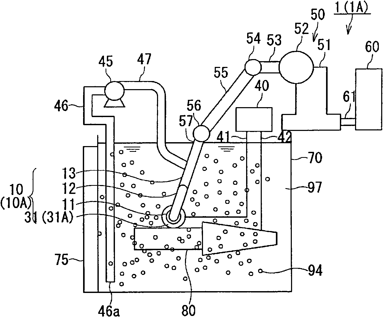
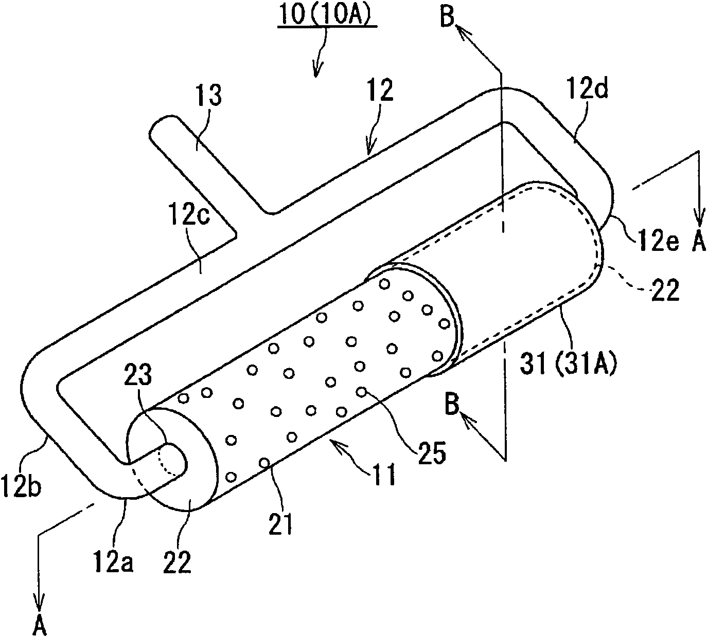
[0056] A first embodiment of the electrolysis apparatus used in the present invention will be described with reference to the drawings. figure 1 is a diagram showing the overall configuration of the electrolysis device 1, figure 2 is a diagram showing a rotating electrode device.

[0057] Such as figure 1 , figure 2As shown, the electrolysis device 1 has the following structural elements. That is to have: an electrolytic cell 70, which is filled with a dispersion liquid 97; a rotating electrode device 10, which is arranged to immerse the rotating drum part 11 having a cylindrical rotating electrode 21 in the dispersion liquid 97; The rotating drum part 11 of this rotating electrode device 10 is used to make the rotating drum part 11 move in the dispersion liquid 97; the control device 60 controls the activity of the manipulator 50; connected so that the dispersion liquid 97 is ejected from the rotating drum part 11; and the stirrer 75 for stirring the dispersion liquid 9...

no. 2 Embodiment approach

[0152] Next, a second embodiment of the electrolysis apparatus used in the present invention will be described with reference to the drawings. In the electrolysis device 1A shown in the second embodiment, in the electrolysis device 1 shown in the first embodiment, a rotating electrode device 10A is used instead of the rotating electrode device 10, and the suction port 46a of the suction side pipe 46 is provided for capturing An unillustrated filter for the MCrAlY powder 94 .

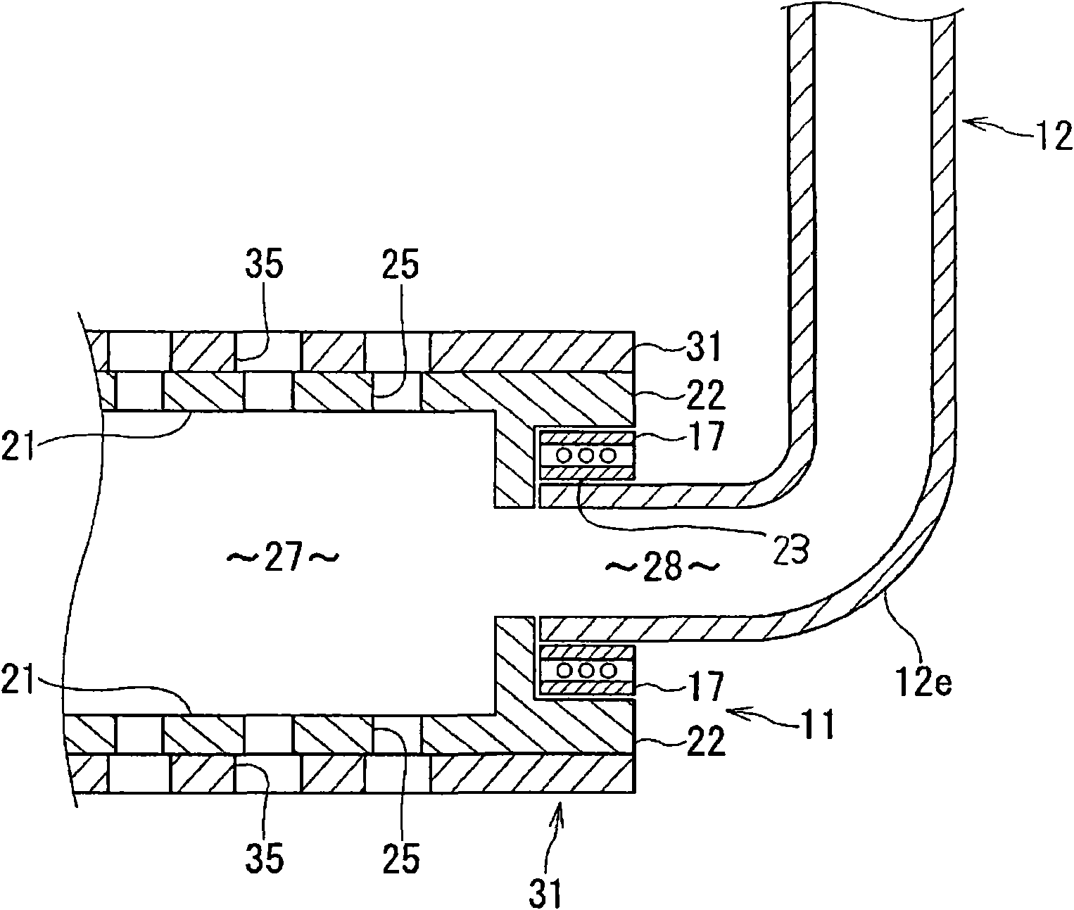
[0153] In the rotating electrode device 10A, a nonwoven fabric layer 31A is used instead of the nonwoven fabric layer 31 in the rotating electrode device 10 described above. The rotating electrode device 10A is the same as the rotating electrode device 10 except for the nonwoven fabric layer 31 and the nonwoven fabric layer 31A. Therefore, the same reference numerals are assigned to the same components, and descriptions of the structures and functions are omitted or simplified.

[0154] The appearance a...

no. 3 Embodiment approach

[0171] Next, a third embodiment of the electrolysis apparatus used in the present invention will be described with reference to the drawings. The electrolysis device 1B shown in the third embodiment has a configuration in which a rotating electrode device 10B is used instead of the rotating electrode device 10 in the electrolysis device 1 shown in the first embodiment, and the dispersion liquid supply pump 45 is not provided.

[0172] The rotating electrode device 10B is used in the rotating electrode device 10 Figure 11 The rotary drum section 11A is shown instead of the rotary drum section 11, and the nonwoven fabric layer 31A used in the second embodiment is used instead of the nonwoven fabric layer 31.

[0173] The rotating electrode device 10B and the rotating electrode device 10 are the same except for the difference between the rotating drum part 11 and the rotating drum part 11A and the difference between the nonwoven fabric layer 31 and the nonwoven fabric layer 31A,...


PUM

PropertyMeasurementUnit
diameteraaaaaaaaaa
particle diameteraaaaaaaaaa
porosityaaaaaaaaaa

Abstract

The present invention provides a coating method, in which a composite coating layer is formed on a surface of an alloy base member by utilizing a rotary electrode device. The coating method includes the steps of: preparing an electrolytic solution containing A ion wherein A is Co or Ni; preparing a MCrAlY powder wherein M denotes at least one element selected from the group consisting of Ni and Co, and the MCrAlY powder contains at least Ni when A is Co or the MCrAlY powder contains at least Co when A is Ni; preparing a dispersion liquid by dispersing the MCrAlY powder into the electrolytic solution; immerging the cylindrical rotary electrode (21) and the alloy base member (80) into the dispersion liquid, using the cylindrical rotary electrode (21) capable of turing and the rotary electrode apparatus (10) of the nonwoven fabric layer (31) covering the surface of the cylindrical rotary electrode (21, and electrolyzing the surface of the alloy base member while the cylindrical rotary electrode covered with the nonwoven fabric layer is rolled on the on the surface of the alloy base member thereby to form the composite coating layer onto the surface of the alloy base member.

Description

technical field [0001] The present invention relates to a coating method for heat-resistant components used in high-temperature oxidizing atmospheres, corrosive atmospheres, etc., and particularly relates to a coating method for heat-resistant components such as gas turbines and jet engines. Background technique [0002] Gas turbine power generation is attracting attention because of the efficient use of energy resources. In gas turbine power generation, high-temperature and high-pressure combustion gas discharged from the combustor is introduced into the main body of the steam turbine, and the shaft of the generator directly connected to the rotor blade is rotated to generate power. [0003] Generally speaking, since the higher the inlet temperature of the gas turbine, the higher the thermal efficiency of the gas turbine, the stator blades and moving blades of the gas turbine exposed to high temperature and high pressure are required to have high heat resistance. [0004] ...

Claims


Application Information

Patent Timeline
Patent Type & Authority Applications(China)
IPC IPC(8): C25D15/00C25D5/04C25D5/12C25D5/08
CPCC25D15/02Y02T50/672C25D5/50F05B2230/90C25D17/18F05D2230/90C25D17/14F01D5/288C25D5/08C25D5/06Y02T50/60
Inventor 斋藤正弘吉冈洋明北山和弘冈本浩明酒井义明
Owner KK TOSHIBA
Why Eureka
Try Eureka