Door lock with rfid key

A key and door lock technology, applied in the field of electronic door locks, can solve problems such as the inability to support independent systems, the power cannot match the battery life, and achieve the effect of saving electricity

Inactive Publication Date: 2006-10-11
COMPIZED SECURITY SYST
View PDF0 Cites 7 Cited by
  • Summary
  • Abstract
  • Description
  • Claims
  • Application Information

AI Technical Summary

Problems solved by technology

On the downside, the power required by this system cannot match the life of the existing battery and therefore cannot support such a self-contained system

Method used


Image

  • Door lock with rfid key
  • Door lock with rfid key
  • Door lock with rfid key

Examples


Embodiment Construction

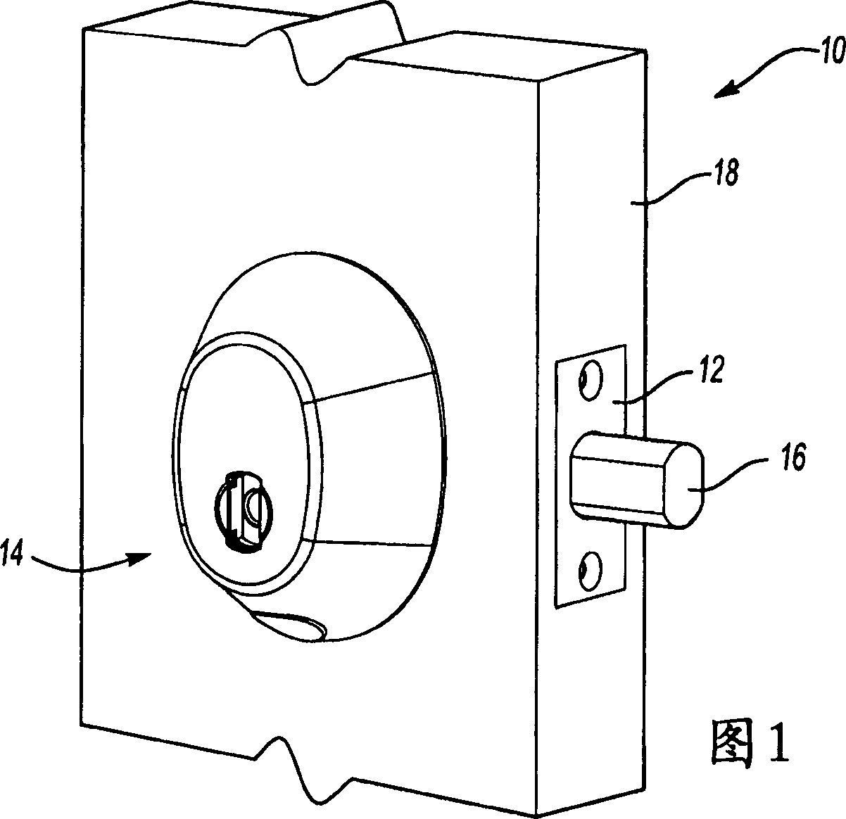
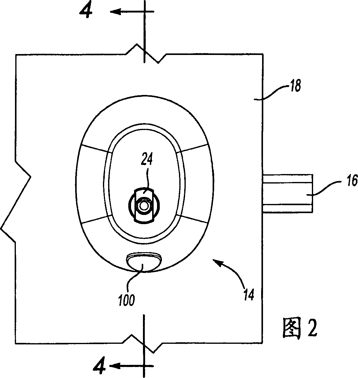
[0017] Referring to FIGS. 1 and 2 , the door assembly 10 includes a latch assembly 12 provided with a primary deadbolt 16 . The primary deadbolt 16 extends from the latch assembly 12 to engage a door jam (not shown) to prevent the door assembly 10 from being opened. Door 18 also includes an electronic lock assembly 14 . The electronic lock assembly 14 corresponds to and actuates the latch assembly 12 to extend and retract the main bolt 16 . The electronic lock assembly 14 includes a keyhole 24 for insertion of a key 88 (FIG. 3). The electronic lock assembly 14 also includes a removable plug 100 that provides access to internal electrical connections provided in the lock assembly 14 .

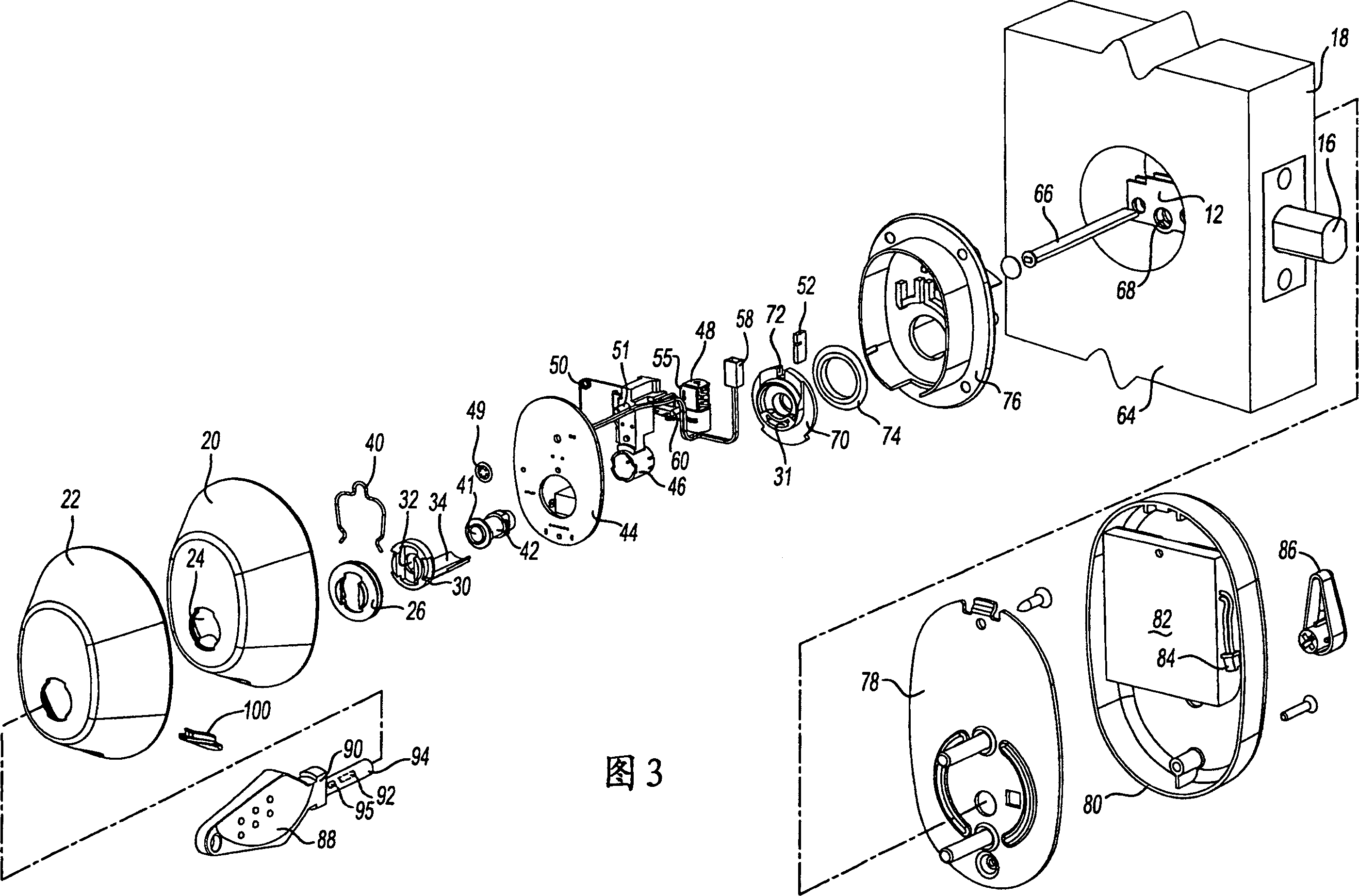
[0018] Referring to FIG. 3 , various corresponding components of the lock assembly 14 are shown in an exploded view. The lock assembly 14 includes a housing 20 that houses several different internal mechanisms. The housing 20 is an oval, dome-shaped member that defines an interior cavity wit...


PUM


Abstract

An electronic lock assembly is actuated by a key including a transponder. The key is received within a coil assembly of the lock assembly. The key engages a switch that powers the coil assembly. The coil assembly generates a magnetic field that energizes the transponder. The transponder transmits a signal received by a controller. The controller actuates the lock assembly responsive to the received signal to move a locking member to an unlocked position. The key may then move to unlatch a latch associated with the lock assembly. As the key provides the energy required for unlatching the latch further energization of the motor is not required. The lock assembly provides for the actuation and energization of the transponder with small amounts electrical energy such that the lock assembly may be powered by commercially available batteries for a practical operational life.

Description

technical field [0001] The invention relates to an electronic door lock. More particularly, the present invention relates to an electronic door lock utilizing a radio frequency identification tag to operate and allow access. Background technique [0002] Typically, electronic door locks use one of several credentials to allow access to the door lock. This credential typically comes in the form of a magnetic stripe key card, smart card, proximity badge, or simply a pin code. The use of magnetic stripe key cards, smart cards, and proximity tokens all have certain drawbacks. In many applications, the lock may include a card reader into which a key card or smart card may be inserted. Key cards and smart cards may include a magnetic strip that stores a code or other access law that can be read by the electronic lock. If the code on the keycard or smart card matches certain predetermined criteria, the electronic lock allows entry and opens the latch. Disadvantageously, smart ...

Claims


Application Information

Patent Timeline
Patent Type & Authority Applications(China)
IPC IPC(8): E05B49/00E05B19/00
CPCE05B15/1614E05B47/0673E05B65/0032E05B2047/0031E05B2047/0058G07C9/00309G07C2009/00777
Inventor M·J·赖特C·W·穆恩E·K·米切尔T·A·特兰M·L·贝格尔M·列梅尼S·M·沃尔德伦
Owner COMPIZED SECURITY SYST
Why Eureka
Try Eureka