
Capacitive high-side switch driver for a power converter

A high-side switching, capacitive technology, applied in electronic switches, circuits, electrical components, etc., can solve the problems of increasing the cost and complexity of the driving circuit, the voltage source and ground reference will interfere, and achieve the effect of strong noise immunity

Inactive Publication Date: 2006-10-11
SYST GEN
View PDF3 Cites 17 Cited by
  • Summary
  • Abstract
  • Description
  • Claims
  • Application Information

AI Technical Summary

Problems solved by technology

thus increasing the cost and complexity of the drive circuit
In addition, due to the high frequency charging and discharging of the voltage doubler capacitor in the charge pump, the voltage source and the ground reference can cause serious interference

Method used


Image

  • Capacitive high-side switch driver for a power converter
  • Capacitive high-side switch driver for a power converter
  • Capacitive high-side switch driver for a power converter

Examples


Embodiment Construction

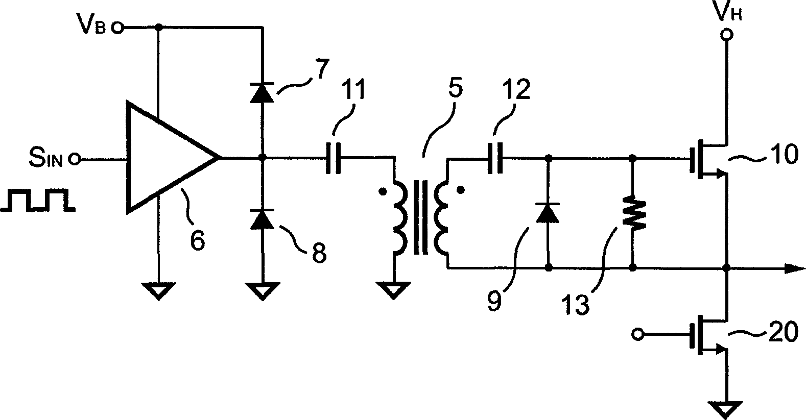
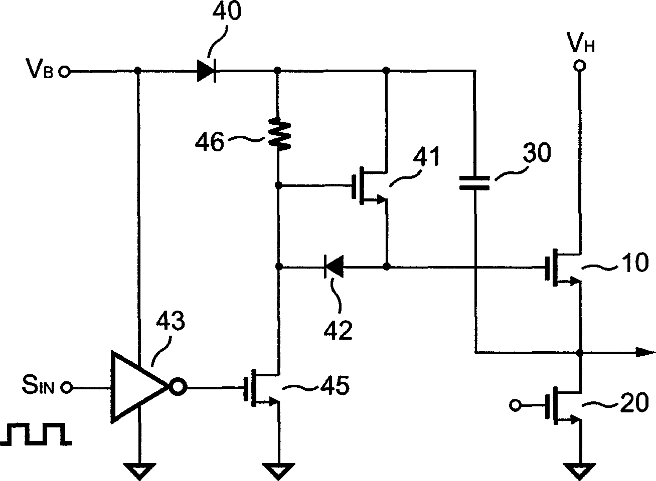
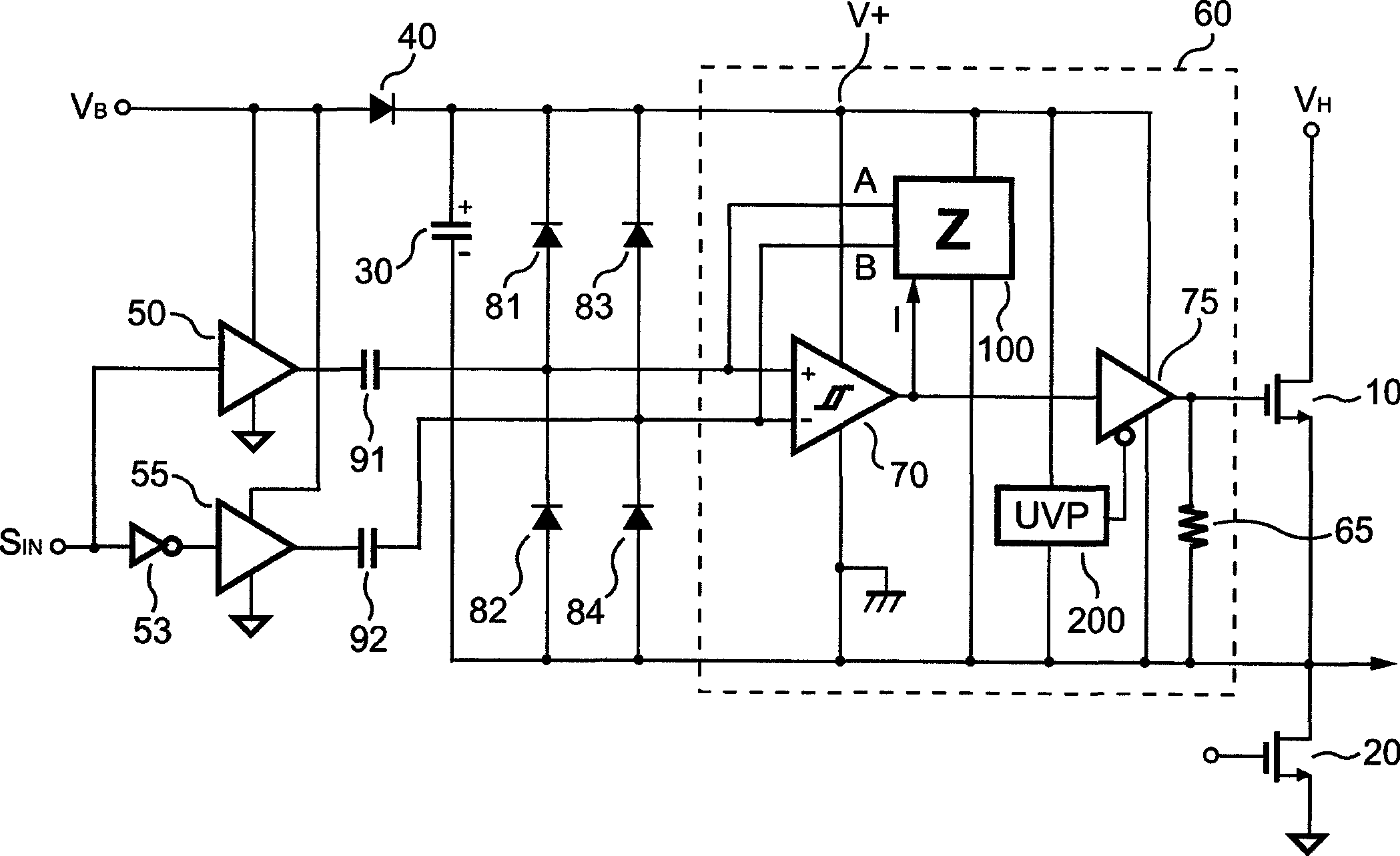
[0025] image 3 A capacitive high-side switch driver according to the present invention is shown. It includes an inverter 53 , a totem pole buffer 50 and a totem pole buffer 55 . Totem pole buffers 50 and 55 are controlled by an input signal S IN And alternating conduction makes its duty cycle complementary. input signal IN Totem pole buffer 50 is driven and totem pole buffer 55 is driven via inverter 53 . An output of the totem pole buffer 50 drives a capacitor 91 . An output of totem pole buffer 55 drives a capacitor 92 . A high-side circuit 60 has an output terminal for driving a high-side transistor 10 , wherein capacitors 91 and 92 are coupled to an input of the high-side circuit 60 . Totem pole buffers 50 and 55 and capacitors 91 and 92 generate differential signals and generate a differential voltage at the input of high side circuit 60 .

[0026] A charge-pump diode 40 and a bootstrap capacitor 30 are connected in series. An anode of charge pump 40 is coupled t...


PUM


Abstract

The present invention discloses a capacitive high-side switch driver for a power converter. The capacitive high-side switch driver according to the present invention includes an inverter and two alternately conducting totem-pole buffers with complementary duty cycles. The duty cycles alternate in response to an input signal. The capacitive high-side switch driver further includes a low-side transistor and a high-side transistor. Once the low-side transistor is turned on, a bootstrap capacitor is charged to create a floating voltage via a charge-pump diode to supply power for the high-side switch driver. To supply additional power for the high-side switch driver, differential signals are produced to further charge the bootstrap capacitor via a bridge rectifier. The capacitive high-side switch driver utilizes a programmable load to provide variable impedance. This strengthens the noise immunity of the circuit. Furthermore, an under-voltage protector supervises the supply voltage to ensure a reliable gate driving voltage.

Description

technical field [0001] The present invention relates to a high-side switch driver, and more particularly, to a driver circuit for driving a high-side switch of a power converter. Background technique [0002] Many common power converters utilize bridge circuits to regulate a voltage source with the state of a load. Some of these power converters include power supplies and motor drives, among others. [0003] The bridge circuits used by these power converters are typically constructed from a pair of switching devices connected in series across a voltage source. The switching device includes a high-side switch and a low-side switch. The high-side switch is connected to a voltage source, while the low-side switch is connected to a ground reference. A common node between the high-side switch and the low-side switch is coupled to the load. The aforementioned switches are typically transistor devices (MOSFETs, IGBTs, etc.). The high-side switch and the low-side switch are con...

Claims


Application Information

Patent Timeline
Patent Type & Authority Applications(China)
IPC IPC(8): H02M1/08H02M1/00H03K17/0412H03K17/06
CPCH03K2217/0081H03K17/04123H03K17/063
Inventor 杨大勇
Owner SYST GEN
Learn More