Chemical vapor deposition method

A technology of chemical vapor deposition and equipment, which is applied in the direction of gaseous chemical plating, electrical components, coatings, etc., and can solve problems such as uneven plasma and thin film deposition

Inactive Publication Date: 2006-10-18
WONIK IPS CO LTD
View PDF1 Cites 135 Cited by
  • Summary
  • Abstract
  • Description
  • Claims
  • Application Information

AI Technical Summary

Problems solved by technology

However, it has the disadvantage that the film cannot be uniformly deposited on the substrate with a large area due to the inhomogeneity of the plasma directly introduced into the chamber.

Method used


Image

  • Chemical vapor deposition method
  • Chemical vapor deposition method
  • Chemical vapor deposition method

Examples


no. 1 example

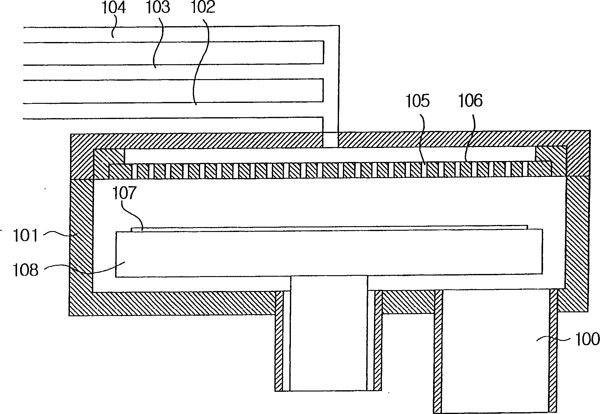
[0034] Figure 2A is a schematic diagram showing structural elements of a radical assisted chemical vapor deposition apparatus capable of sequentially supplying process gases according to the first embodiment of the present invention.

[0035] As can be seen from this figure, the chemical vapor deposition equipment involved in the present invention has such a structure that it is formed by sequentially supplying process gas including the steps of injecting and cleaning source gas and injecting and cleaning reaction gas. Films in which reactive gases are injected in such a state that plasma is generated in the shower head after they are injected.

[0036] Such as Figure 2A As shown in , in the chemical vapor deposition equipment involved in the present invention, the top plate 212 is installed on the top of the chamber 201 and constitutes a part of the chamber 201, the RF power supply connection part 209 that can be connected with the external RF power supply 210 Mounted on ...

no. 2 example

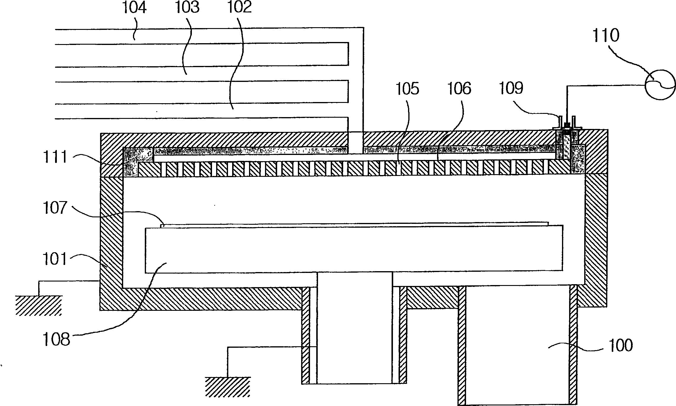
[0051] Figure 3A is a structural element representing a radical assisted chemical vapor deposition apparatus capable of sequentially supplying process gases and generating plasma in the upper portion of a shower head partitioned in a predetermined manner according to the second embodiment of the present invention A schematic diagram of .

[0052] As can be seen from this figure, the chemical vapor deposition equipment involved in the present invention has such a structure that it is formed by sequentially supplying process gas including the steps of injecting and cleaning source gas and injecting and cleaning reaction gas. thin film; by separating the shower head into two parts to separate the first part into which the source gas is introduced and injected from the second part into which the reaction gas is introduced and injected, the mixing between the source gas and the reaction gas can be completely prevented; After the reaction gas, radicals of the reaction gas may be e...

no. 3 example

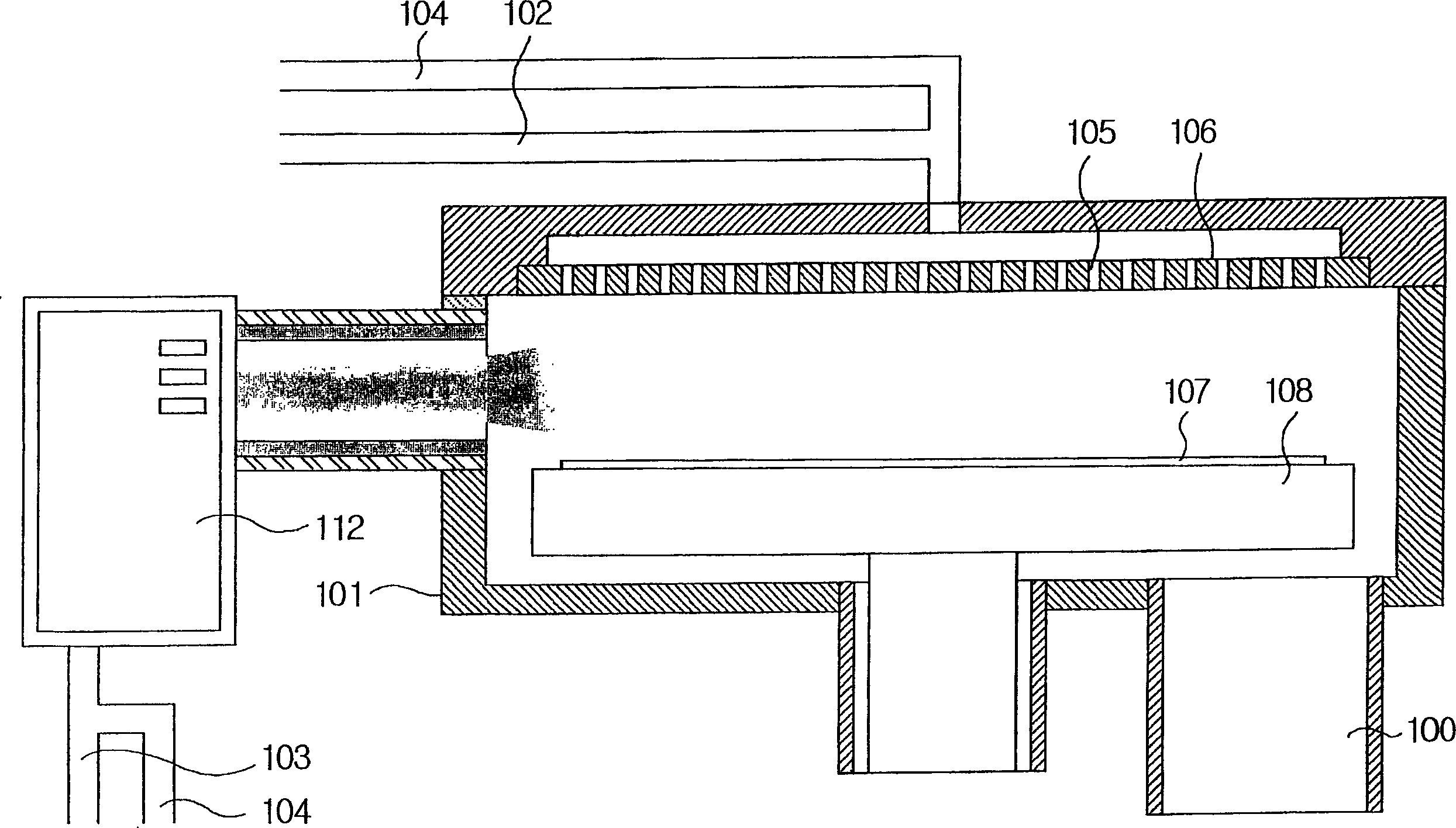
[0066] Figure 4 is a schematic diagram showing structural elements of a chemical vapor deposition apparatus capable of sequentially supplying process gases and using an external plasma generating apparatus according to a third embodiment of the present invention.

[0067] As shown in the figure, the chemical vapor deposition equipment involved in the present invention includes a chamber 401 with an outlet 400 in the lower part, a nozzle 406 in which a plurality of injection holes 405 for injecting process gas are formed, and a support for supporting A wafer or substrate 407 (hereinafter referred to as “substrate”) and simultaneously a heater 408 serving as a heat source enables thin film deposition on the substrate 407 by process gas injected through the shower head 406 .

[0068] A top plate 409 is mounted on top of the chamber 401 and forms part of the chamber 401 . External plasma generating devices 410 are connected to the chamber 401 and communicate with each other outs...


PUM


Abstract

The present invention relates to chemical vapor deposition apparatus. In the chemical vapor deposition apparatus, an RF power source connection portionconnected to an external RF power source is installed on an upper side of a chamber; an RF electrode plate is installed within the chamber to be spaced with a predetermined gap from an inner upper surface of the chamber and to be spaced with a predetermined gap from a showerhead disposed below the RF electrode plate; plasma is generated in a first buffer portion, which is defined by a gap between the RF electrode plate and an upper surface of the showerhead, by means of the electric power applied from the external RF power source to the RF electrode plate; the showerhead is divided into two sections in a vertical direction and a second buffer portion is defined by a space between the two sections; reactant gases are supplied to the first buffer portion in which the plasma is generated; and source gases are supplied to the second buffer portion.

Description

[0001] This application is a divisional application of an invention patent application with the application number 02107463.1, the filing date being March 19, 2002, and the invention title being "Chemical Vapor Deposition Equipment". technical field [0002] The present invention relates to a chemical vapor deposition (CVD) apparatus. In particular, the present invention relates to a chemical vapor deposition apparatus that uses radicals of reaction gases while sequentially supplying process gases by generating plasma within a showerhead or ejecting external plasma into a chamber using the showerhead. Background technique [0003] Generally, source gas and reaction gas are sequentially supplied into a chemical vapor deposition apparatus in order to obtain excellent layered coating and film quality characteristics at low temperature. Here, will refer to Figure 1A to Figure 1C A brief description will be given of a conventional chemical vapor deposition apparatus capable of s...

Claims


Application Information

Patent Timeline
Patent Type & Authority Applications(China)
IPC IPC(8): C23C16/513H01L21/205C23C16/448
CPCC23C16/45536C23C16/45544C23C16/45565C23C16/5096C23C16/513H01J37/32082H01J37/3244H01J37/32532
Inventor 金宰湖朴相俊
Owner WONIK IPS CO LTD
Why Eureka
Try Eureka