Band conveyer for conveying fleece

A technology for conveyor belts and whiskers, applied in the field of conveyor belts, can solve the problems of weakening the air permeability of conveyor belts, late detection of compression effects, and danger.

Inactive Publication Date: 2006-10-18
MASCHINENFABRIK RIETER AG
View PDF1 Cites 4 Cited by
  • Summary
  • Abstract
  • Description
  • Claims
  • Application Information

AI Technical Summary

Problems solved by technology

[0005] The disadvantage of such conveyor belts made of polyamide is that they do not slide particularly well over a suction channel with suction grooves
These strongly adhering contaminants accumulate on the conveyor belt over time and thus reduce the compressive effect of the unit, because the gas permeability of the conveyor belt is reduced
This is particularly dangerous because it is a slow process, as the loss of compression is often not noticed until very late

Method used


Image

  • Band conveyer for conveying fleece
  • Band conveyer for conveying fleece

Examples


Embodiment Construction

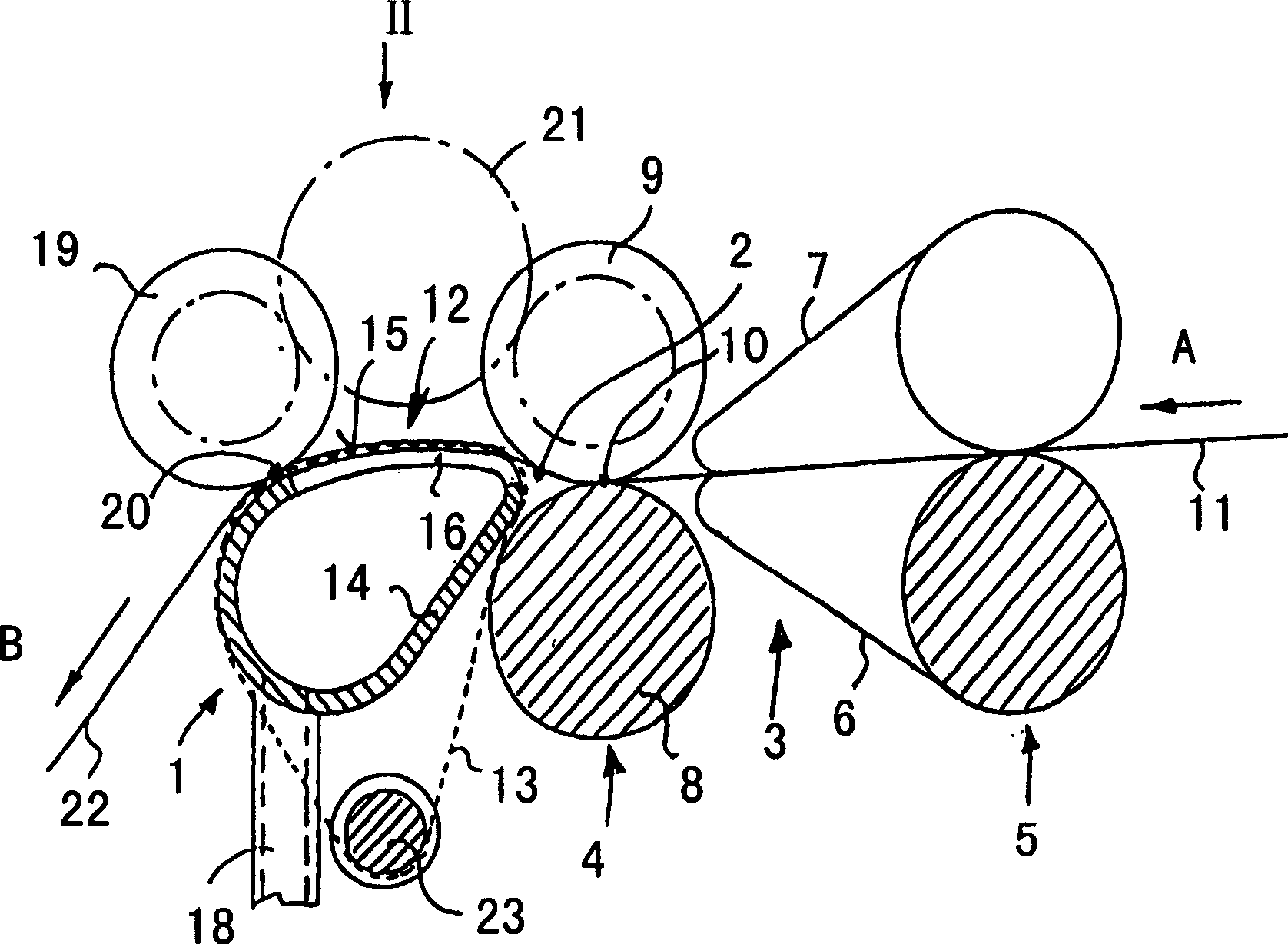
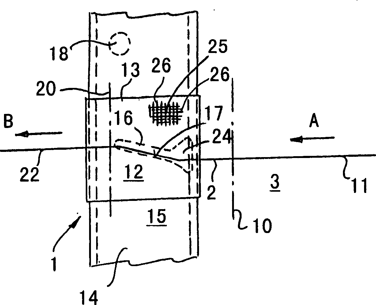
[0016] With regard to spinning machines, especially a ring spinning machine, in figure 1 with 2 Only the position of the device 1 for compressing a stretched fiber strand 2 that has not yet been spun and twisted has been shown. The device 1 is directly connected to a tensioning mechanism 3, of which only the pair of output rollers 4 and a pair of belt rollers arranged in front of it in the direction of transport A and having a lower belt 6 and an upper belt 7 are shown. The output roller pair 4 includes a driven output lower roller 8 and an output pressure roller 9 elastically pressed against it. The delivery roller pair 4 defines the delivery nip line 10 , which forms the end of the stretching zone of the stretching mechanism 3 .

[0017] In the stretching unit 3 , the fiber strip or also the roving 11 can be stretched in a known manner in the transport direction A to the desired fineness. Stretching ends at the output nip line 10, and from this position onwards is the str...


PUM


Abstract

A textile machine has a conveyer belt for a fiber feed to a pneumatic compression zone. The conveyer belt consists of plastic filaments and is air-permeable. The belt weave incorporates poly-tetrafluorethylene (PTFE) applied either as a coating, or embedded within the plastic filaments.

Description

technical field [0001] The invention relates to a conveyor belt for transporting a fiber strand to be compressed pneumatically, which consists of an air-permeable fabric made of synthetic filaments at least in the region of a guide fiber strand. Background technique [0002] If on a spinning machine, the output roller directly connected to the stretching mechanism carries out spinning and twisting to the stretched fiber sliver, then a so-called spinning triangle is produced on the jaw line of the output roller pair. This thus results in a stretched fiber strand having a certain width leaving the stretching mechanism and twisted into a yarn of relatively small diameter. The spinning triangle contains edge yarns which are not woven into the twisted yarn in an orderly manner and therefore have little or no effect on the strength of the spun yarn. Consequently, people have recently tended to arrange a so-called compression zone after the stretching zone of the stretching mechan...

Claims


Application Information

Patent Timeline
Patent Type & Authority Applications(China)
IPC IPC(8): D03D1/00D01H5/26
CPCD01H5/72D01H5/86
Inventor G·施塔莱克P·布兰肯霍恩
Owner MASCHINENFABRIK RIETER AG
Why Eureka
Try Eureka