Hydraulic damper

A hydraulic damper and oil technology, applied in the field of hydraulic dampers, can solve problems such as insufficient damping force, and achieve the effects of rapid elimination of inflation, reduction of overall length, and simplification of structure

Inactive Publication Date: 2006-10-18
HITACHI LTD
View PDF1 Cites 15 Cited by
  • Summary
  • Abstract
  • Description
  • Claims
  • Application Information

AI Technical Summary

Problems solved by technology

[0007] In this way, in the damper for washing machines, it is required to have: a sufficiently large damping force is generated to suppress the shaking of the drum during resonance, and the damping force characteristics such as reducing the damping force and absorbing the vibration of the drum in normal times are required. In the above-mentioned Patent Document 1 The announced damper for washing machines satisfies this requirement to a certain extent, but its damping force tends to be insufficient at resonance, and there is room for further improvement

Method used


Image

  • Hydraulic damper
  • Hydraulic damper
  • Hydraulic damper

Examples


Embodiment Construction

[0036] Embodiments of the present invention will be described in detail below according to the accompanying drawings.

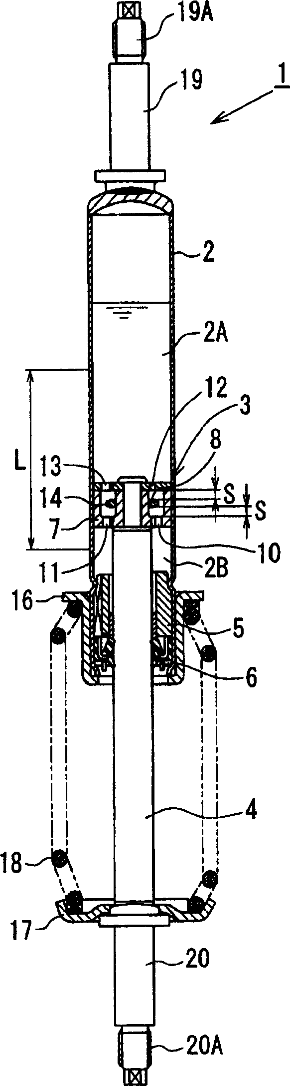
[0037] Such as figure 1 As shown, in the hydraulic damper 1 of the first embodiment of the present invention, the piston 3 is slidably embedded in the bottomed cylindrical cylinder 2, and the cylinder 2 is divided into the cylinder upper chamber 2A and the cylinder upper chamber 2A by the piston 3. Two chambers of lower chamber 2B. One end of the piston rod 4 is connected to the piston 3, and the other end of the piston rod 4 extends outward through the piston rod guide 5 and the oil seal 6 installed in the opening of the cylinder 2, and the connection between the cylinder 2 and the piston rod 4 is connected through the oil seal 6. The space is sealed, and the inside of cylinder 2 is sealed. The oil and gas are mixed and sealed in the cylinder 2, the piston 3 is immersed in the oil, and there are no distinguishing parts such as free pistons at the boundary ...


PUM


Abstract

A hydraulic damper that produces a small damping force for small-amplitude vibrations and a large damping force for large-amplitude vibrations in a hydraulic damper for washing machines. A piston (3) connected with a piston rod (4) is slidably embedded in a cylinder (2) in which oil and gas are mixed and sealed, and immersed in the oil. The extension side oil passage (10) and the shortening side hole (11) are arranged at the bottom of the piston body (7), and the shortening side oil passage (12) and the extension side hole (13) are arranged on the cover part (8). The body (14) is arranged axially movable inside the piston (3). When the piston rod is at a small amplitude, the moving distance of the valve body (14) is small, and the oil passages (10) and (12) on the extension side and the shortening side are opened, so a small damping force is generated. The moving distance of (14) becomes larger, and the valve body (14) closes the extension side and shortening side oil passages (10), (12), so a large attenuation force.

Description

technical field [0001] The present invention relates to a hydraulic damper which can be used as a damper for a washing machine or the like for supporting a water tank in which a drum of a drum type washing machine is accommodated. Background technique [0002] Generally speaking, in a drum type washing machine such as a fully automatic washing machine, it has a rotating shaft that is approximately horizontal to the ground, and a substantially cylindrical water tank that accommodates a drum with laundry and is rotatably supported and becomes the washing machine. Springs and dampers are installed between the boxes of the outer contour of the machine, and the water tank is suspended by these springs and dampers, so as to absorb and stop the vibration generated by the rotation of the drum. [0003] As general dampers used in drum-type washing machines, friction dampers and hydraulic dampers are known. A friction damper generates a damping force through sliding friction of a fri...

Claims


Application Information

Patent Timeline
Patent Type & Authority Applications(China)
IPC IPC(8): D06F37/22
Inventor 内藤博克高岩聪户川竜太村田广志
Owner HITACHI LTD
Why Eureka
Try Eureka