
Two-stroke engine

An engine, two-stroke technology, applied in engine components, combustion engines, machines/engines, etc., can solve problems such as large design space, and achieve the effects of simple structure, high cost, and low cost

Inactive Publication Date: 2006-10-18
DOLMAR
View PDF4 Cites 1 Cited by
  • Summary
  • Abstract
  • Description
  • Claims
  • Application Information

AI Technical Summary

Problems solved by technology

Two-stroke engines can be designed such that high exhaust backpressure is generated at high speeds, but this cannot be achieved at low speeds
Unfortunately this device requires a large design space and cannot always be effectively used in the field of two-stroke internal combustion engines

Method used


Image

  • Two-stroke engine
  • Two-stroke engine
  • Two-stroke engine

Examples


Embodiment Construction

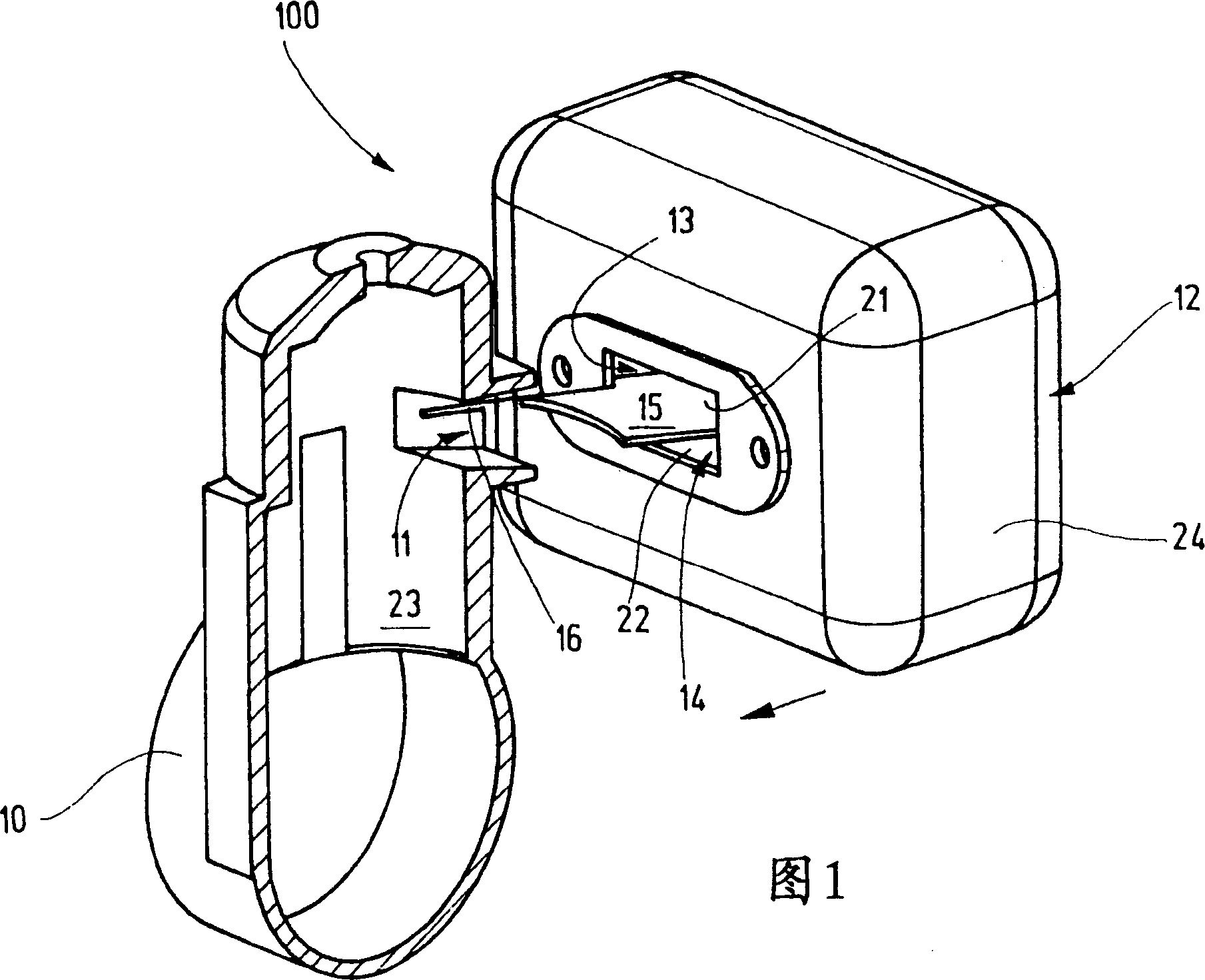
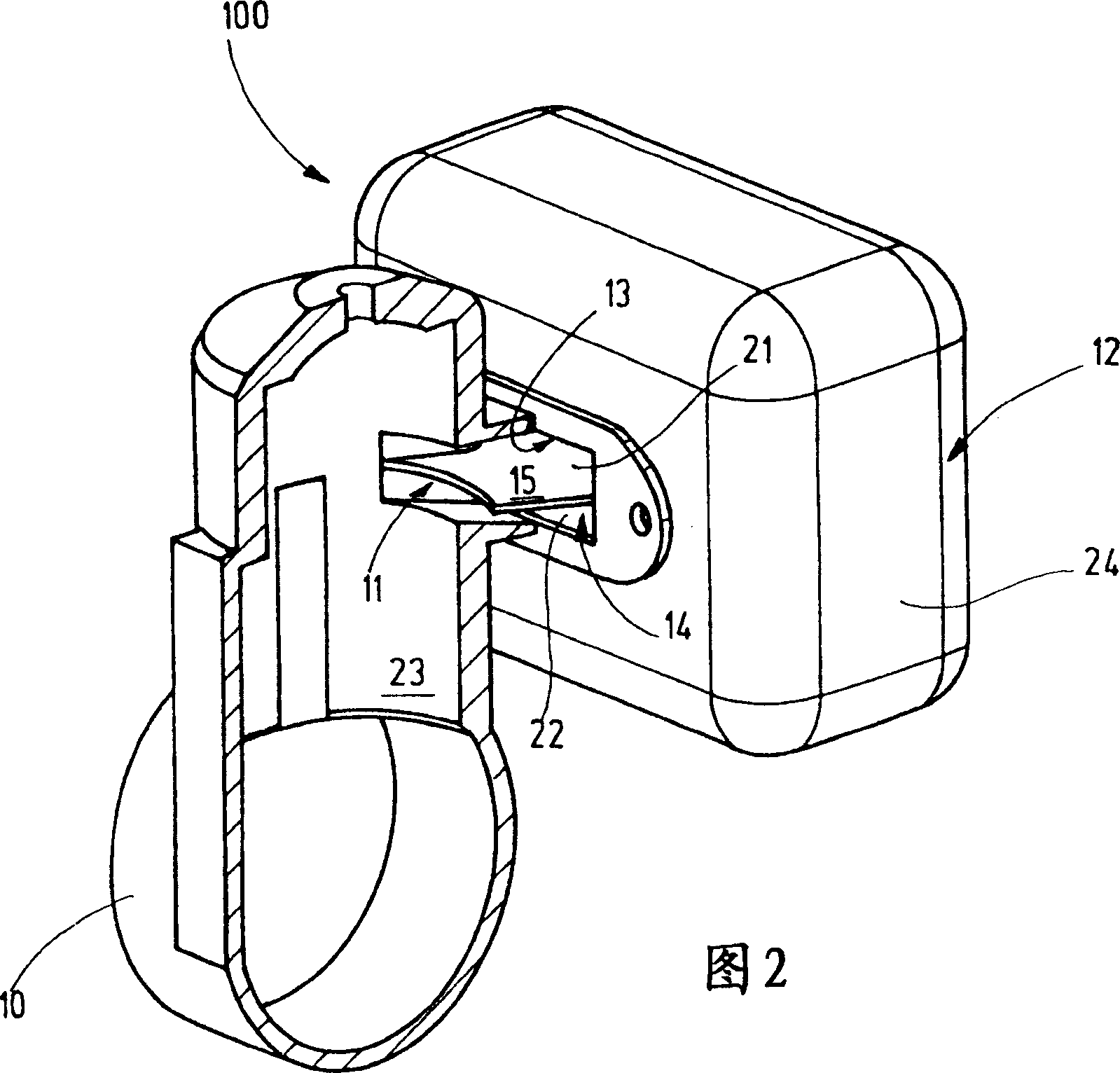
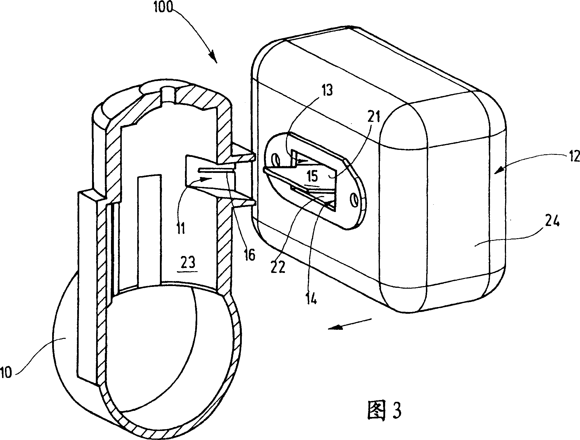
[0037]Figure 1 shows a cylinder 10 of a two-stroke engine 100 having a working volume 23 in which the piston moves and having an exhaust outlet 11 in the form of a duct. The lateral duct wall has fastening means 126 in the form of two grooves 16 (only one groove 16 is shown because it is shown in section), wherein the grooves 16 end at a certain distance from the working volume 23 . Mounted on the cylinder 10 is a muffler 12 having a first chamber 13 and a second chamber 14 surrounded by a common housing wall 24 . The first chamber 13 and the second chamber 14 are separated from each other by a wall, not shown, located inside the housing wall 24 . A bypass is provided between the two chambers, also not shown. The muffler 12 has an inlet which is divided by a partition 15 , thus forming an upper opening 21 and a lower opening 22 . The upper opening 21 is connected to the first chamber 13 as a buffer chamber, and the lower opening 22 is connected to the second chamber 14 . Th...


PUM


Abstract

In order to provide a two-stroke engine ( 100 ) which has an exhaust outlet ( 11 ) on the cylinder ( 10 ), with a silencer ( 12 ) arranged on the exhaust outlet ( 11 ), which silencer comprises a first chamber ( 13 ) and a second chamber ( 14 ) which are connected to the exhaust outlet ( 11 ) and through which exhaust gas produced in the cylinder ( 10 ) is able to flow, wherein the first chamber ( 13 ) is designed so that it is largely closed, and the exhaust gas can be guided through the second chamber ( 14 ) via an outlet on the silencer side into the open air, in which the disadvantages are avoided, and with which, in particular, a simple, compact unit is produced which at the same time effectively prevents damaging post-escape to the largest possible extent, it is proposed that the exhaust outlet ( 11 ) is designed with fixing means ( 16, 17, 18 ) on which a partition ( 15 ) is detachably arranged, which partition guides some of the exhaust gas into the first chamber ( 13 ) and some into the second chamber ( 14 ).

Description

technical field [0001] The invention relates to a two-stroke engine, which has an exhaust outlet on the cylinder, and a muffler is arranged on the exhaust outlet, the muffler includes a first chamber and a second chamber, the first chamber and the second chamber are connected to the exhaust Exhaust gases on the outlets and generated in the cylinder can flow through them, wherein the first chamber is designed to be substantially closed, and the exhaust gases can be led through the second chamber and flow into the air through the exhaust outlet. Background technique [0002] It is generally known to use devices on two-stroke engines to reduce or avoid damaging post-escape of unburned fuel-air mixture. The lower the exhaust back pressure the more fresh gas escapes into the exhaust system, which is connected in series to the two-stroke engine, and the higher the exhaust back pressure the less fresh gas reaches the engine cylinders middle. Two-stroke engines can be designed suc...

Claims


Application Information

Patent Timeline
IPC IPC(8): F02B25/20
CPCF01N1/02F01N13/10F01N2260/14F01N2490/10F02B25/14F02B25/20F02B33/04F02B2075/025
Inventor C·克勒曼
Owner DOLMAR
Learn More