Roll core and electrode body manufacturing method using same

A manufacturing method and electrode body technology, applied in secondary battery manufacturing, winding/folding electrodes, battery electrodes, etc., can solve the problems of electrode body quality degradation, separator tearing, and core cost increase, and achieve the purpose of suppressing damage , prevent slipping, and prevent quality reduction

Active Publication Date: 2006-10-18
MAXELL HLDG LTD
View PDF4 Cites 10 Cited by
  • Summary
  • Abstract
  • Description
  • Claims
  • Application Information

AI Technical Summary

Problems solved by technology

Therefore, in Patent Documents 1 to 3, the positional relationship between the positive electrode and the negative electrode is shifted due to the slip of the separator during winding, resulting in a decrease in the quality of the electrode body.
[0009] On the other hand, in Patent Documents 4 and 5, the diaphragm is clamped and fixed by the divided winding core to prevent the above-mentioned sliding of the diaphragm. are squeezed at the same time, so the diaphragm may be torn
Moreover, Patent Documents 4 and 5 may cause cost up of winding cores due to their complex structures.

Method used


Image

  • Roll core and electrode body manufacturing method using same
  • Roll core and electrode body manufacturing method using same
  • Roll core and electrode body manufacturing method using same

Examples


Embodiment Construction

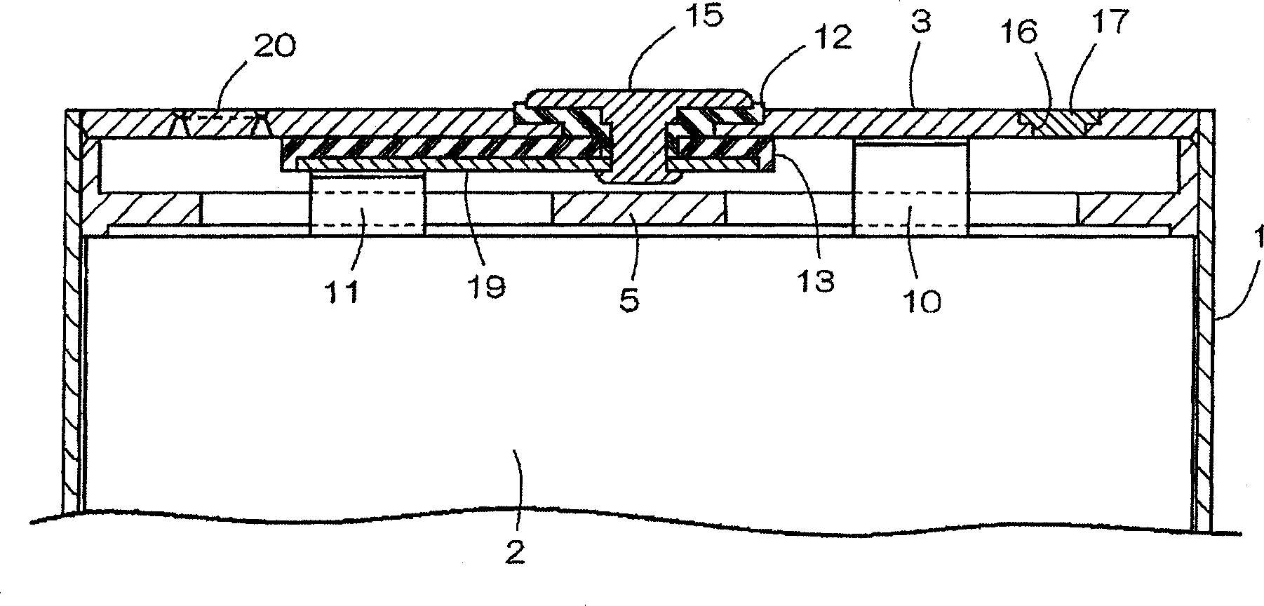
[0027] exist image 3 and Figure 4 Among them, the thin and sealed rectangular battery of the present invention comprises: a bottomed square battery case 1 with long left and right lateral openings; an electrode body 2 and a non-aqueous electrolyte contained in the battery case 1; the opening of the battery case 1 is blocked The upper left-right laterally long cover 3 and the plastic insulator 5 disposed inside the cover 3 are provided. The battery case 1 is a clad material made of nickel and aluminum, which is deep-drawn to form a thin case that is long in the vertical direction. The left and right width of the battery case 1 is 34 mm, the vertical height is 50 mm, and the front and rear thickness is 3.8 mm.

[0028] The electrode body 2 is formed by spirally winding a strip-shaped separator 9 made of a microporous polyethylene film (polyethylene film) between the strip-shaped positive electrode 6 and the strip-shaped negative electrode 7 . After winding, the electrode bo...


PUM


Abstract

The invention provides a winding core with simple structure and capable of clamping and fixing the diaphragm. The winding core (21) includes: the outer shaft (22) for winding the positive electrode (6) and the negative electrode (7) and the diaphragm (9); the central shaft (25) for fixing the diaphragm (9); the outer shaft (25) of the embedded part (35) A receiving shaft (26) embedded in the front end portion (25b) of the central shaft (25). The outer shaft (22) has a space (23) open at one end thereof, and the central shaft (25) is arranged in the space (23). The center shaft (25) has a center shaft slit (29) open at one end thereof. The outer shaft (22) has an outer shaft slot (27) opposite the central shaft slot (29). Insert the two overlapping diaphragms (9, 9) into the central shaft slit (29) through the outer shaft slit (27), and externally fit the embedded part (35) of the receiving shaft (26) into the central shaft (25) When on the front end portion (25b) of the front end (25b), the diaphragm (9) is clamped and fixed by the closed central axis slit (29).

Description

technical field [0001] The present invention relates to a winding core for manufacturing an electrode body contained in a battery case or the like of a lithium ion battery and a method for manufacturing an electrode body using the winding core. Background technique [0002] Patent Documents 1 to 5 disclose a method of manufacturing an electrode body in which a positive electrode, a negative electrode, and a separator are wound in a state where a strip-shaped separator is sandwiched between a strip-shaped positive electrode and a strip-shaped negative electrode by rotating a winding core. onto the aforementioned winding core to manufacture an electrode body. [0003] Patent Document 1: Japanese Patent Laying-Open No. 8-153519 (paragraph 0009-0010, Image 6 —10) [0004] Patent Document 2: Japanese Patent Laying-Open No. 2003-282136 (paragraph 0017, figure 1 ) [0005] Patent Document 3: Japanese Patent No. 536391 (paragraph 0046, figure 2 ) [0006] Patent Document 4: ...

Claims


Application Information

Patent Timeline
IPC IPC(8): H01M10/38H01M6/16H01M10/04H01M10/0587
CPCH01M4/139H01M10/0587Y02E60/10Y02P70/50H01M10/0409H01M10/0431
Inventor 竹轮光博高原知新服部浩
Owner MAXELL HLDG LTD
Why Eureka
Try Eureka