Electrical connector

一种电连接器、连接部的技术,应用在电气元件等方向,能够解决组装作业繁琐、连接器成本变高等问题

Inactive Publication Date: 2006-10-18
TYCO ELECTRONICS JAPAN GK
View PDF1 Cites 3 Cited by
  • Summary
  • Abstract
  • Description
  • Claims
  • Application Information

AI Technical Summary

Problems solved by technology

[0008] That is, by providing the wiring board 110, it is not necessary to produce a plurality of molds (molds of the contacts) according to the form of pitch change, but since the wiring board 102 other than the contacts 104 and 105 needs to be provided in order to change the pitch , so there is still a problem that the cost of the connector becomes higher in terms of the number of parts
In addition, in addition to mounting the contacts 104 and 105 on the insulating frame 103, it is necessary to install the wiring board 102 in the insulating frame 103, so there is a problem that the assembly work is cumbersome.

Method used


Image

  • Electrical connector
  • Electrical connector
  • Electrical connector

Examples


Embodiment Construction

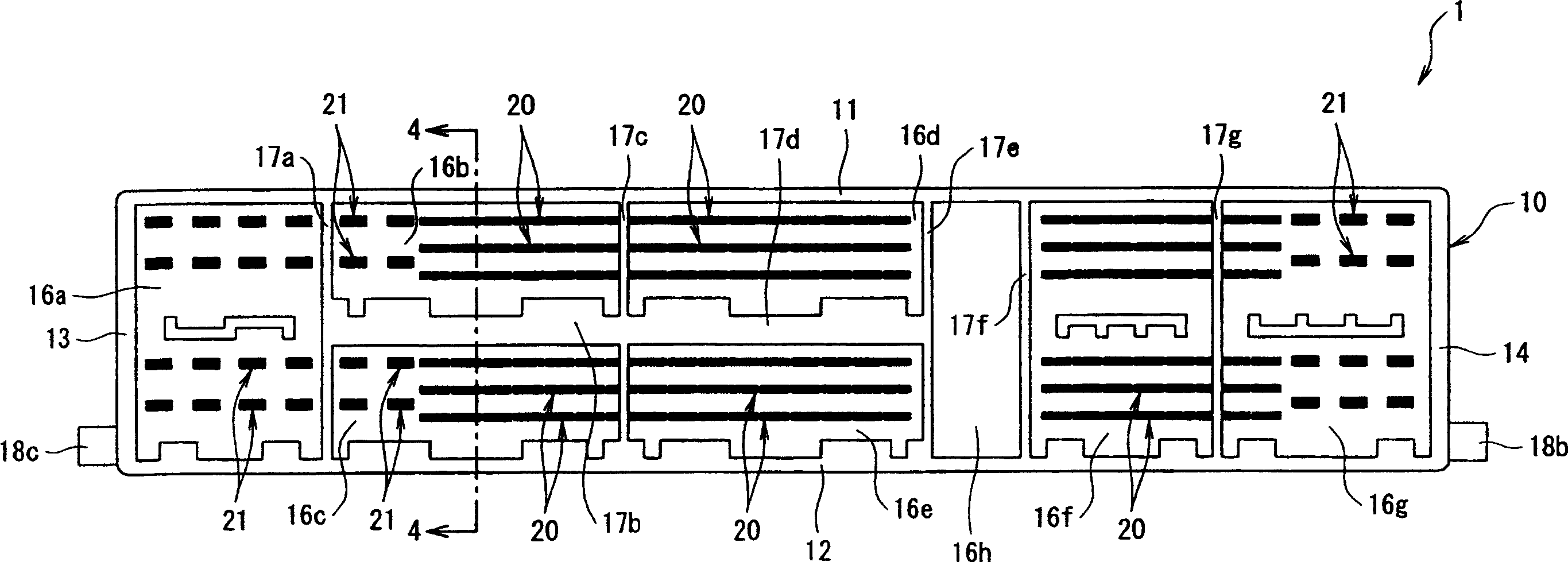
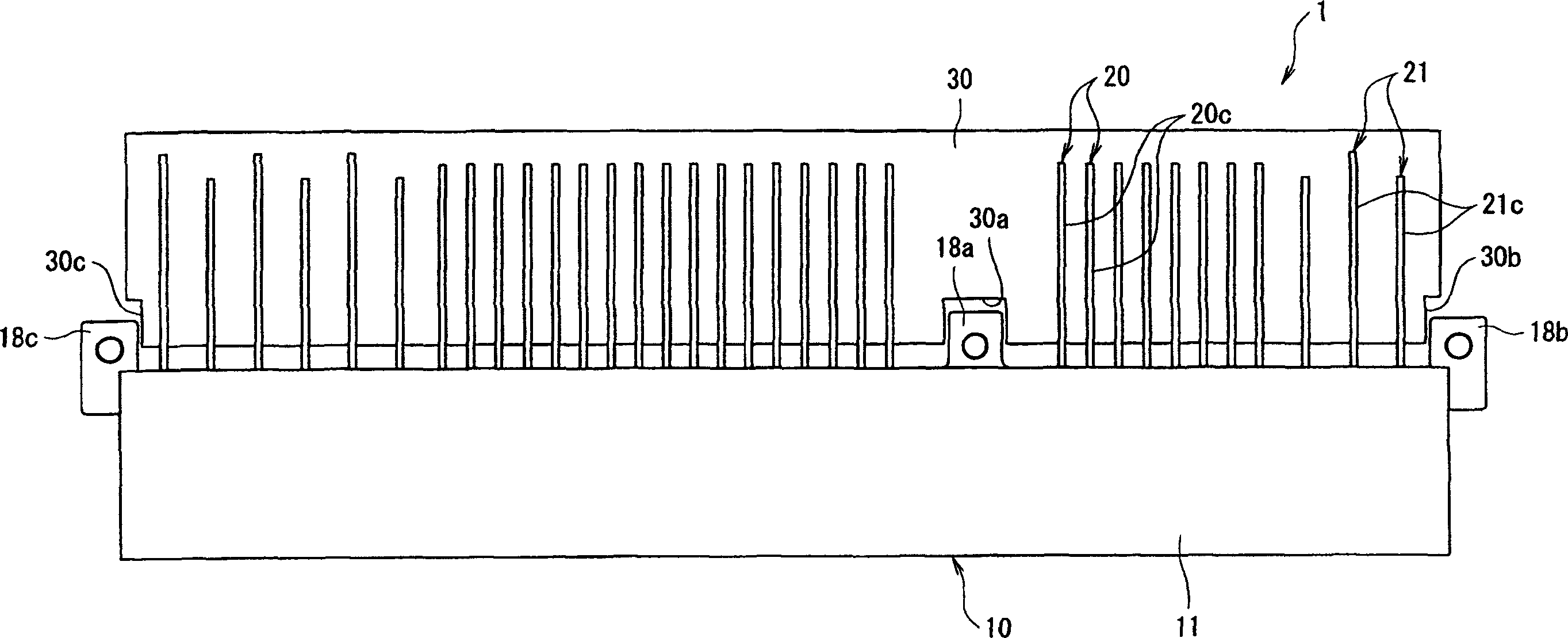
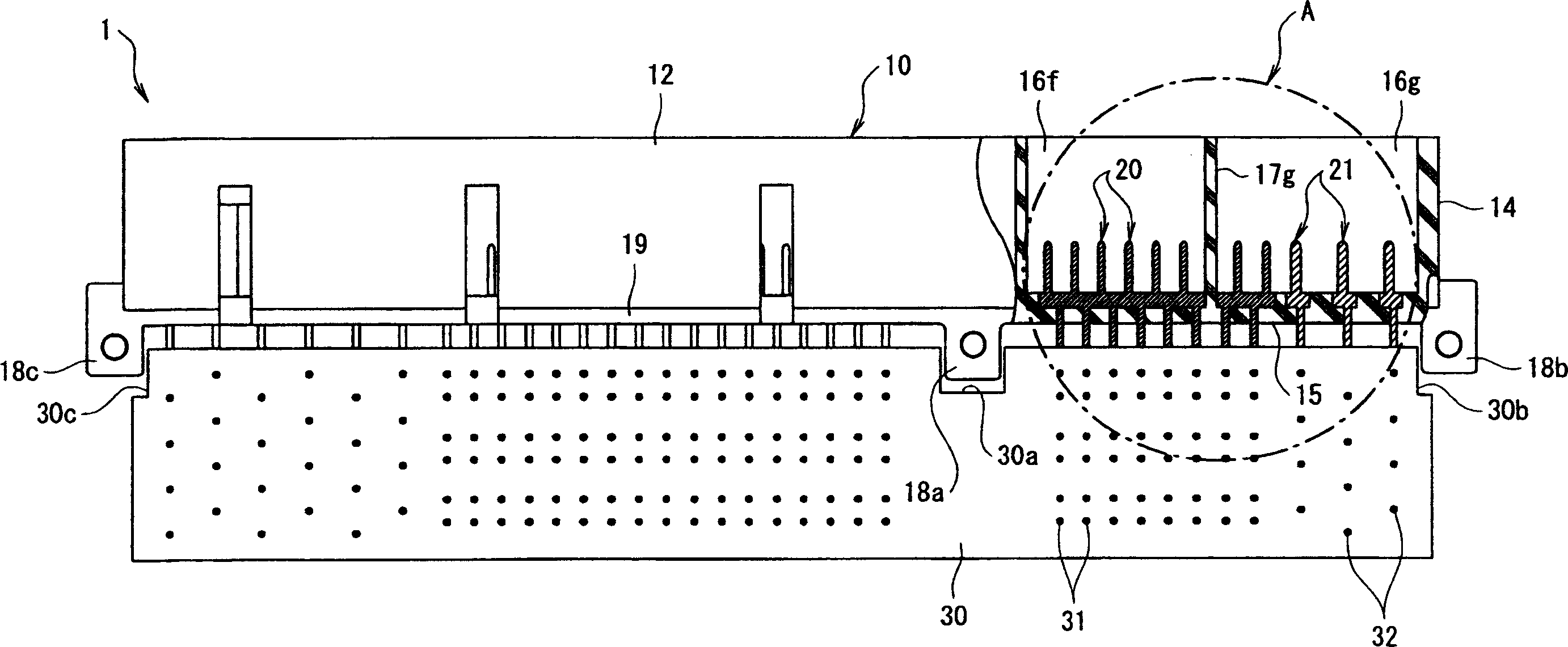
[0022] Hereinafter, embodiments of the present invention will be described with reference to the drawings. figure 1 is a front view of the electrical connector of the present invention. figure 2 Yes figure 1 A plan view of the electrical connector shown. image 3 is true figure 1 A partially cut-away bottom view of the electrical connector shown. Figure 4 is along figure 1 Sectional drawing of the 4-4 lines. Figure 5 Yes image 3 An enlarged view of the portion indicated by arrow A in . Image 6 Yes indicates that the mating connector is mated to the figure 1 Side view of the electrical connector shown on the back state.

[0023] exist Figure 1 to Figure 4 Among them, an electrical connector 1 includes an insulating housing 10 , a plurality of signal contacts 20 and power contacts 21 fixed to the housing 10 , and a tine plate 30 .

[0024] Here, the casing 10 is formed in a substantially rectangular shape having a top wall 11 , a bottom wall 12 , a pair of s...


PUM


Abstract

It is an object of the present invention to provide an electrical connector having a pitch conversion function in which the cost of the connector is low, and the assembly work can be performed easily. In the electrical connector (1), each of the plurality of contacts (20) comprises a securing part (20a), a contact part (20b), and a connecting part (20c), and the center line of the contact part (20b) and the center line of the connecting part (20c) are offset from each other. The plurality of contacts (20) have the same shape. The contacts (20) are disposed so that the pitch (P1) between the connecting parts (20c) of adjacent contacts (20) is the same, and the electrical connector (1) has an area where arbitrary contacts (20) are inverted 180 degrees, and are disposed so that the pitch (P2) between the contact parts (20b) of the arbitrary contacts (20) and the contact parts (20b) of the contacts (20) that are adjacent to these arbitrary contacts (20) is different from the pitch (P1) between the connecting parts (20c).

Description

technical field [0001] The invention relates to an electrical connector with the function of changing distance. Background technique [0002] In the case of connecting a plurality of electronic parts to each other, connecting electronic parts to a circuit board, connecting circuit boards to each other, or connecting a mating connector having contacts connected to a plurality of wires to a circuit board to each other , sometimes using electrical connectors with a pitch change function. [0003] Conventionally, as a pitch conversion connector used when connecting a plurality of electronic components to each other, for example, such as Figure 8 The connector shown (refer to Patent Document 1). Figure 8 It is a plan view of an example of an existing pitch conversion connector. [0004] Figure 8 The shown pitch conversion connector 101 is equipped with a wiring board 102 and an insulating frame 103 is provided around the wiring board 102 . At the insula...

Claims


Application Information

Patent Timeline
Patent Type & Authority Applications(China)
IPC IPC(8): H01R12/00
CPCH01R12/724
Inventor 山上英久实藤雄介
Owner TYCO ELECTRONICS JAPAN GK
Why Eureka
Try Eureka