Constant-velocity joint and image forming device

A speed coupling and coupling technology, which are applied in the field of image forming devices, can solve the problems of large-scale constant speed coupling, increase in the number of parts, increase in cost, etc., so as to improve the degree of freedom of design and reduce the number of parts. , The effect of low working noise

Inactive Publication Date: 2006-10-25
NTN CORP
View PDF1 Cites 71 Cited by
  • Summary
  • Abstract
  • Description
  • Claims
  • Application Information

AI Technical Summary

Problems solved by technology

[0016] Moreover, when used in food manufacturing equipment, the food will be contaminated due to the leakage of grease, so it is necessary to take measures such as installing boots to prevent the leakage of grease, which will reduce the number of parts. increase, the cost also increases accordingly, leading to the large-scale constant velocity coupling
[0017] Moreover, when used in an image forming apparatus, since the dust cover needs to be detached every time the constant velocity coupling is assembled or disassembled, maintenance is difficult.

Method used


Image

  • Constant-velocity joint and image forming device
  • Constant-velocity joint and image forming device
  • Constant-velocity joint and image forming device

Examples


Embodiment Construction

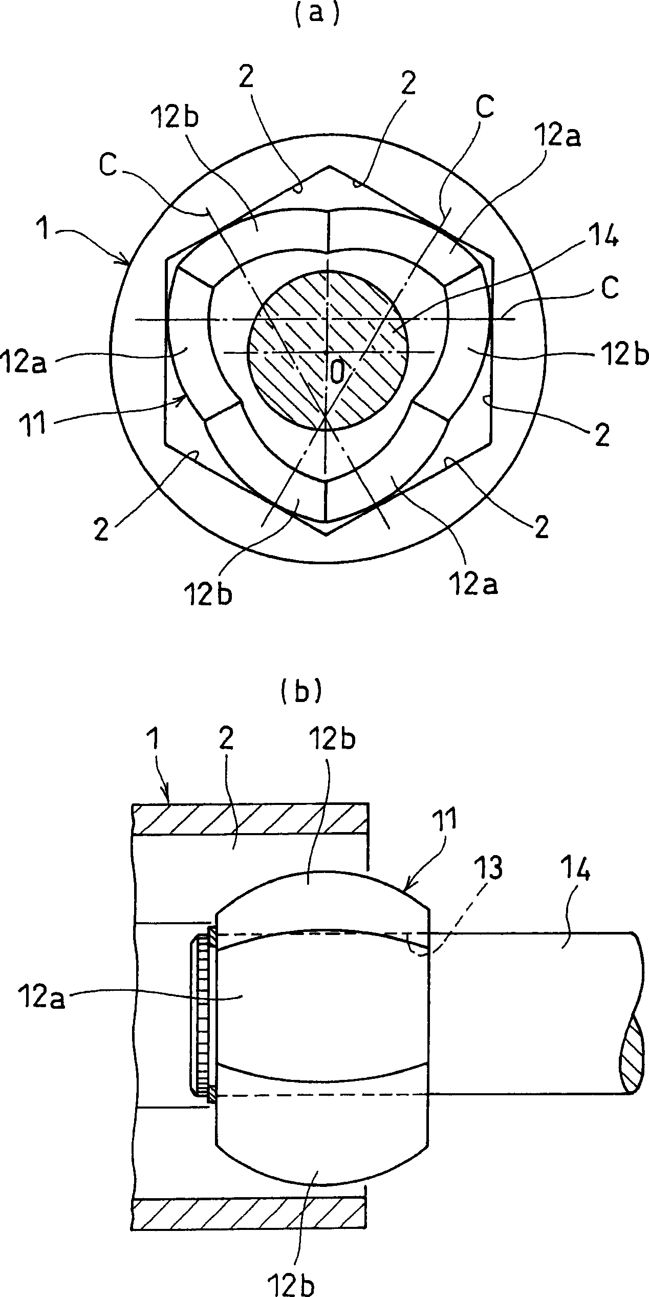
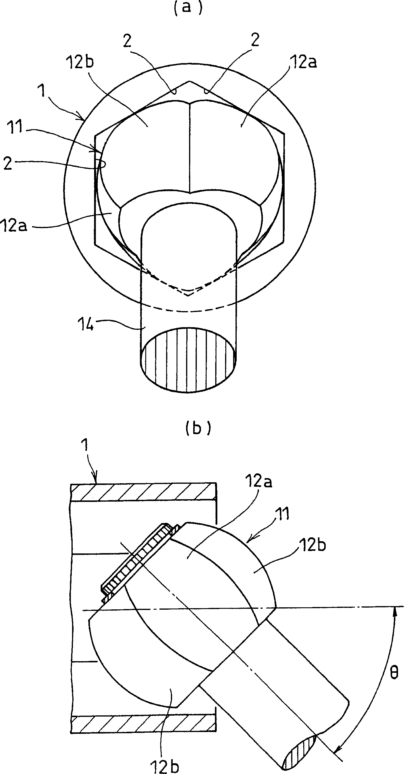
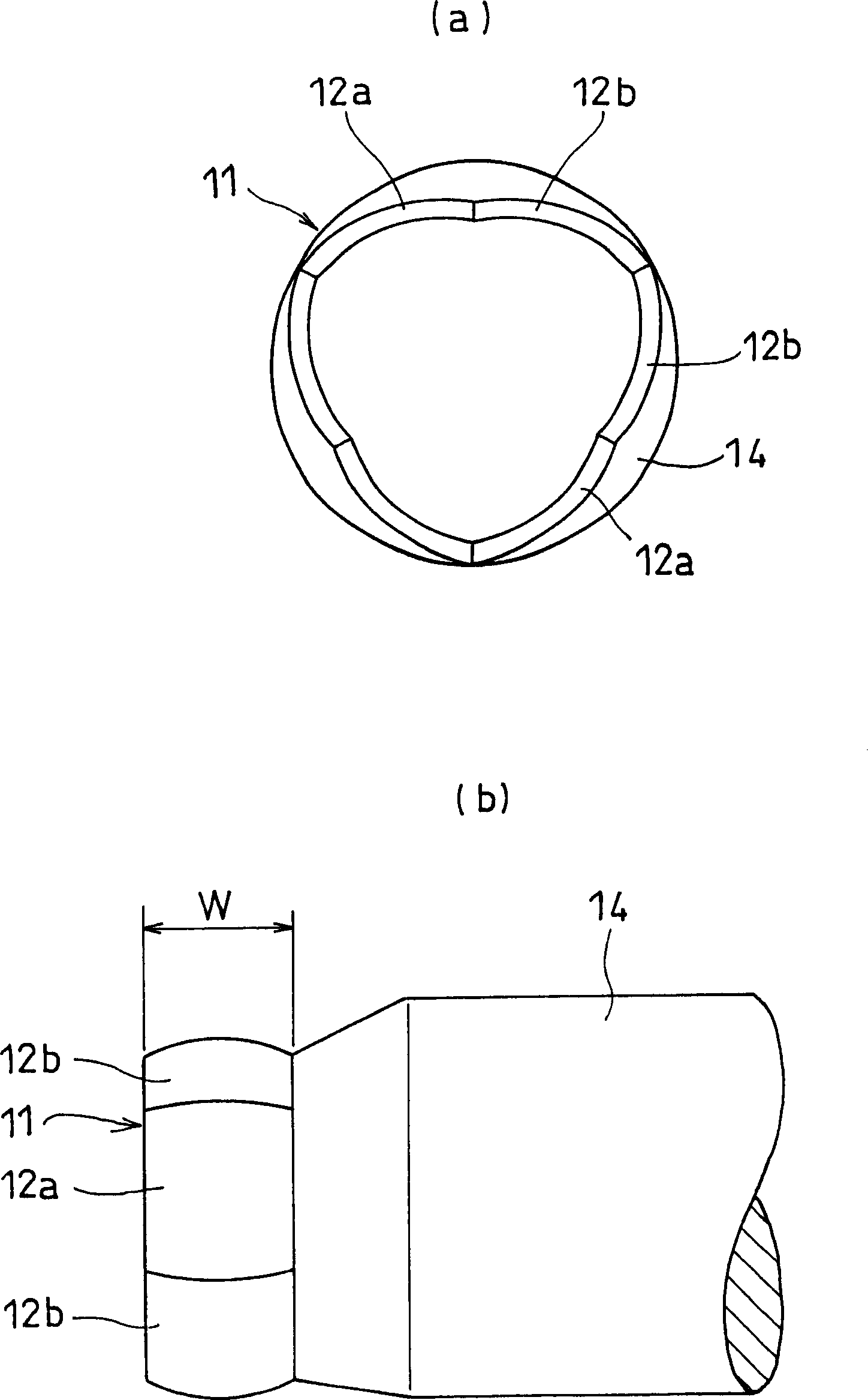
[0039] Hereinafter, embodiments of the present invention will be described with reference to the drawings. Such as figure 1 As shown in (a) and (b), the constant velocity coupling is composed of an outer wheel 1 and a pivot member 11. The outer wheel 1 has a regular hexagonal hollow hole surrounded by six flat surfaces 2 parallel to the axis. The shaft member 11 is assembled in this hollow hole.

[0040] On the outer peripheral surface of the pivot member 11, three first spherical surfaces 12a and three second spherical surfaces 12b that are in contact with the flat surface 2 are alternately formed along the circumferential direction.

[0041] The first spherical surface 12 a is in contact with the flat surface 2 at a position deviated from the central position of the flat surface 2 in the circumferential direction to one side in the circumferential direction (clockwise in the figure). In addition, the second spherical surface 12 b is in contact with the flat surface 2 at a ...


PUM


Abstract

The present invention provides a lightweight constant velocity coupling that does not require grease lubrication. The pivot part (11) is assembled in the outer wheel (1), and the outer wheel (1) has a hexagonal hollow hole surrounded by 6 flat surfaces (2) parallel to the axis, and the pivot part (11 ), a first spherical surface (12a) and a second spherical surface (12b) are formed along the circumferential direction, and the first spherical surface (12a) is biased from the central position of the flat surface (2) in the circumferential direction to the circumferential direction The second spherical surface ( 12 b ) is in contact with the flat surface at a position offset from the central position to the other side in the circumferential direction. Since the outer ring 1 and the pivot member (11) are molded of synthetic resin, grease lubrication is not required, and the weight of the constant velocity coupling can be reduced.

Description

technical field [0001] The present invention relates to a constant velocity joint (joint) that connects two shafts, a drive shaft and a driven shaft, to transmit the power of the drive shaft to the driven shaft, and a copier and a copier using the constant velocity joint. An image forming device of a laser printer (LBP). Background technique [0002] In the past, the known image forming apparatus is as follows, that is, on the outer periphery of the photosensitive drum rotating in one direction, a charger, an exposure mechanism, a developing device, and a transfer charger are provided, and the outer periphery of the photosensitive drum is charged by the above-mentioned charger. After the whole is charged in the same way, the exposure mechanism exposes the image based on the image information to form an electrostatic latent image, and the developer supplies toner to the electrostatic latent image to form a toner image, and then passes through the transfer charger. This toner...

Claims


Application Information

Patent Timeline
Patent Type & Authority Applications(China)
IPC IPC(8): F16D3/16B41J3/00G03G15/00
CPCF16D3/185F16D2001/102
Inventor 大桥正明杉山达朗小林繁夫福泽觉
Owner NTN CORP
Why Eureka
Try Eureka