
Method for realizing upward link back-up

A link backup and downlink technology, applied in data exchange through path configuration, digital transmission system, electrical components, etc., can solve communication interruption, consume multicast user bandwidth, increase IGMP proxy equipment system overhead, etc. , to achieve the effect of reducing the consumption of system resources, ensuring normal operation, and reducing the waste of link bandwidth

Inactive Publication Date: 2006-10-25
HUAWEI TECH CO LTD
View PDF0 Cites 22 Cited by
  • Summary
  • Abstract
  • Description
  • Claims
  • Application Information

AI Technical Summary

Problems solved by technology

When only one uplink is configured, if the uplink is unavailable, all multicast users using the IGMP proxy device will be unable to receive multicast data packets, resulting in communication interruption
When multiple uplinks are configured on the IGMP proxy device, when a certain uplink is unavailable, the IGMP proxy device can ensure that multicast users can use multicast to communicate normally, but in this case, the actual The above is to receive the same multicast data message from the multicast source or multicast router, and copy them to the downlink connected to the multicast user, so that the multicast user actually receives multiple same multicast data packets. datagram
This not only consumes the bandwidth of multicast users, but also increases the system overhead of IGMP proxy equipment

Method used


Image

  • Method for realizing upward link back-up
  • Method for realizing upward link back-up

Examples


Embodiment 1

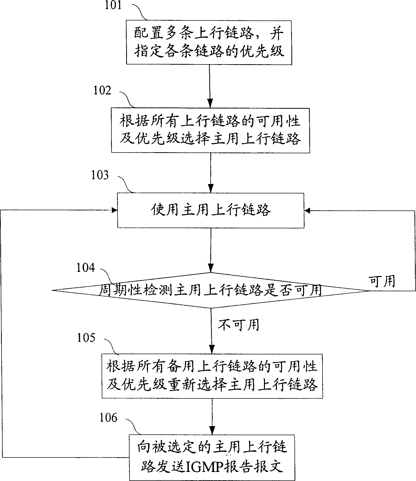
[0038] The specific implementation process of this embodiment is as follows: figure 1 shown, including the following steps:

[0039] Step 101: Configure more than one uplink on the IGMP proxy device according to the existing network topology, and set different priorities for each uplink, and write the priority of each uplink into the respective corresponding In the priority identifier field of the link control block, the priority of the uplink is identified.

[0040] Here, the priority of the uplink can be set according to the following conditions of the uplink, including: idle bandwidth of the uplink, interface type, link delay, IGMP proxy device connected to the multicast source through the uplink or The number of network devices that the multicast router passes through, and whether the uplink is a dedicated uplink or a common uplink. Specifically, for the idle bandwidth of the uplink, the priority of the uplink with larger idle bandwidth is higher; for the interface type ...

Embodiment 2

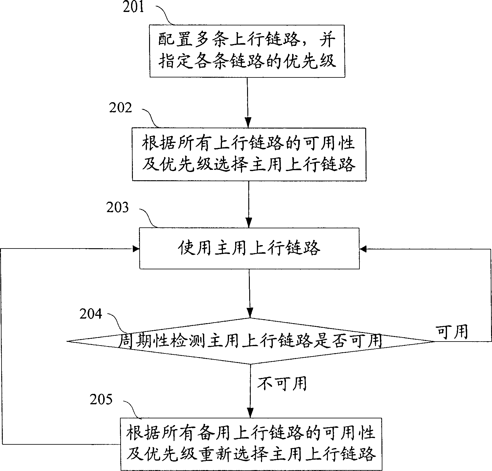
[0061] The specific implementation process of this embodiment is as follows: figure 2 shown, including the following steps:

[0062] Steps 201-202: the same as steps 101-102 in the first embodiment.

[0063] Step 203: The IGMP proxy device simultaneously sends IGMP report messages to the active uplink and all backup uplinks, and also responds to IGMP query messages received from the active uplink and all backup uplinks. However, the IGMP proxy device still only receives multicast data packets from the active uplink and copies them to the downlink connected to the multicast user; discards the multicast data packets received from the standby uplink . The IGMP proxy device distinguishes the active / standby uplink by detecting the active / standby identification field in the link control block corresponding to the uplink, and distinguishes the IGMP protocol message and the multicast message according to the IP protocol field in the IP header of the received message. Data message,...


PUM


Abstract

The method configures more than one up going link for each IGMP proxy device, and sets up priority for each up going link. The method also includes following steps: (1) selecting main up going link based on usability and priorities of all up going links; and ensuring that the rest of up going link are as standby going links; (2) determining whether it is needed to select new main up going link; if yes, then executing step (3); otherwise, returning back to step (2); (3) selecting new main up going link based on usability and priorities of all standby up going links; then returning back to step (2). Comparing prior art, where only one up going link is available, the method prevents multicast users of using IGMP proxy device from unable to implement normal communication. Moreover, comparing with IGMP proxy device, which uses multiple up going links, the method reduces wastage of link bandwidth, and lowers consumption of system resources.

Description

technical field [0001] The invention relates to multicast technology, especially a method for realizing uplink backup on an Internet Group Management Protocol (IGMP) agent device. Background technique [0002] The multicast source or multicast router uses IGMP to manage the process of multicast users joining and leaving a multicast group, and the process of multicast users receiving multicast data packets from the multicast source or multicast router. In actual network implementation, not all multicast users are directly connected to multicast sources or multicast routers. Multicast users are often connected to multicast sources or multicast routers through network devices. Here, the network equipment includes Layer 2 and Layer 3 network equipment, wherein the Layer 2 network equipment is such as a Layer 2 Ethernet switch, and the Layer 3 network equipment is such as a router. Due to the different manufacturers of network devices, some support multicast routing protocols, a...

Claims


Application Information

Patent Timeline
Patent Type & Authority Applications(China)
IPC IPC(8): H04L12/24H04L12/28
CPCH04L12/1886H04L41/0668H04L43/0811H04L45/00H04L45/16H04L45/22H04L45/28H04L69/40
Inventor 胡杰晖任斌熊宇曹亮怀南
Owner HUAWEI TECH CO LTD
Learn More