Linear actuator with fast releaser

A linear actuator and release technology, applied in the direction of transmission, belt/chain/gear, mechanical equipment, etc., can solve the problems of limited use range and complicated mechanism design, and achieve the effect of increasing safety and reducing impact force

Inactive Publication Date: 2006-11-01
HIWIN MIKROSYST
View PDF2 Cites 13 Cited by
  • Summary
  • Abstract
  • Description
  • Claims
  • Application Information

AI Technical Summary

Problems solved by technology

However, this type of loosening mechanism must include a planetary gear set; when loosening, the internal teeth and planetary gears must not only rotate on their own, but also revolve around the sun gear, and the loosening slider also needs to convert the axial force into a radial force. Therefore, the design of the mechanism is complicated, and the release mechanism must cooperate with the linear actuator and the design of the planetary gear set can be used to add the release mechanism, thus limiting the scope of use of this type of release mechanism

Method used


Image

  • Linear actuator with fast releaser
  • Linear actuator with fast releaser
  • Linear actuator with fast releaser

Examples


Embodiment Construction

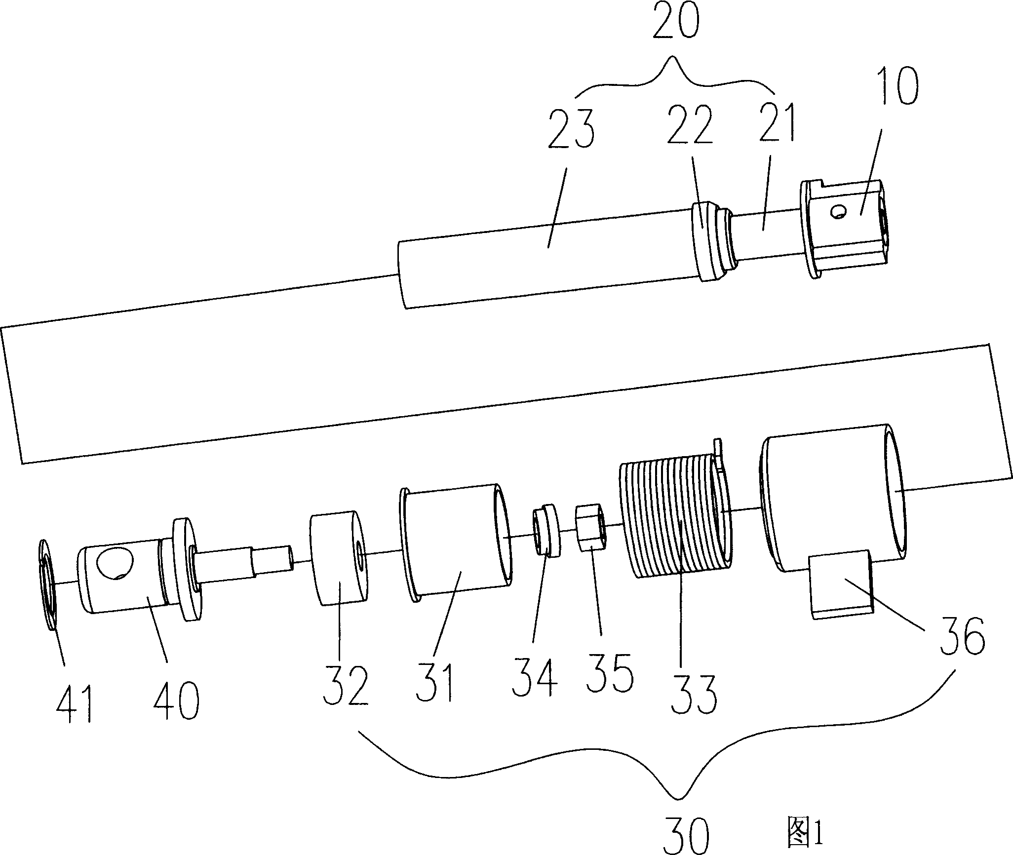
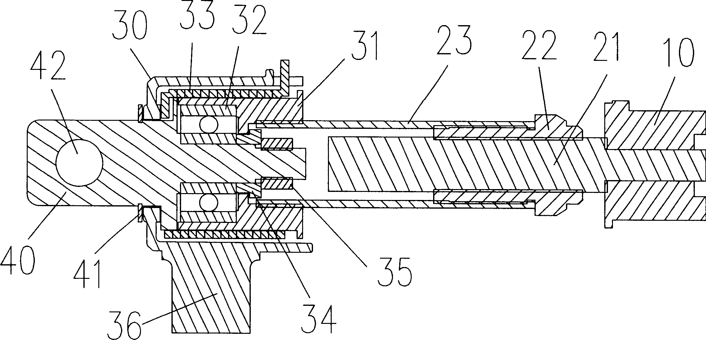
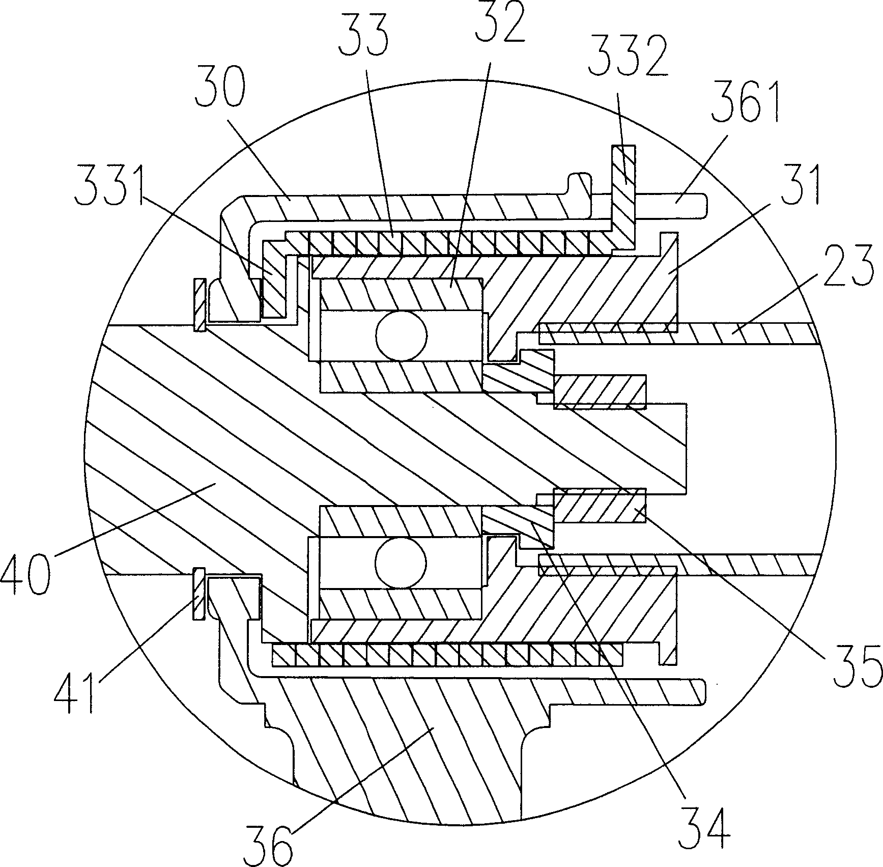
[0028] Fig. 1 is a three-dimensional exploded view of a linear actuator with a quick release mechanism in the present invention; wherein the power device 10 is a power source that outputs rotational torque, and transmits the torque from the motor to a transmission device 20, and the transmission device 20 includes a screw shaft 21. The nut 22 and the inner tube 23, and there is a quick release device 30 between the transmission device 20 and the load joint 40; the screw shaft 21 is connected to the power device 10 to transmit power, and the nut 22 fits on the screw shaft 21 to The rotational torque is converted into linear motion, and the inner tube 23 is fixed on the nut 22 to move with the nut 22. The rear end of the inner tube 23 is fixed on the inner edge of the front end of the loose sleeve 31, and the outer diameter of the loose sleeve 31 is set A loosening spring 33 is combined, and a loosening handle 36 is placed outside the loosening spring 33; the inner edge of the re...


PUM


Abstract

A linear actuator with a quick loosing device mainly includes a power unit, a driving unit, a load joint and a quick loosing device. The quick loosing device disposed between the driving unit and the load joint mainly consists of a rotating part, a non-rotating part and a loosing spring. The lacing force of the loosing spring can bind or separate the rotating part and the non-rotating part and can also transfer the power.

Description

technical field [0001] The present invention is a linear actuator with a quick release device. The linear actuator is used on a reciprocating machine equipment for extending and retracting, and the quick release device releases the Mechanism design for load recovery. Background technique [0002] A general linear actuator is mainly composed of a motor, an output shaft, a transmission shaft, a screw shaft, a nut, and an inner tube. First, the motor transmits the rotational torque to the output shaft. Because the output shaft and the transmission shaft are axially connected, The rotational torque of the output shaft can be transmitted to the transmission shaft, and the transmission shaft is provided with a screw shaft, a nut is fitted on the screw shaft and an inner tube is connected to the nut; when the screw shaft rotates with the transmission shaft, the nut The rotational force of the screw shaft is converted into a linear thrust or pull, so that the inner tube makes a rec...

Claims


Application Information

Patent Timeline
Patent Type & Authority Applications(China)
IPC IPC(8): F16H25/20
Inventor 刘宗城林佳论
Owner HIWIN MIKROSYST
Why Eureka
Try Eureka