
Road roller capable of automatically adjusting water yield
An automatic adjustment, road roller technology, applied in the direction of roads, roads, road repairs, etc., can solve the problems of inconvenience, uneven road surface, inability to water out of the variable speed of the road roller, etc., and achieve the effect of simple structure
- Summary
- Abstract
- Description
- Claims
- Application Information
AI Technical Summary
Problems solved by technology
Method used
Image

Examples
Embodiment Construction
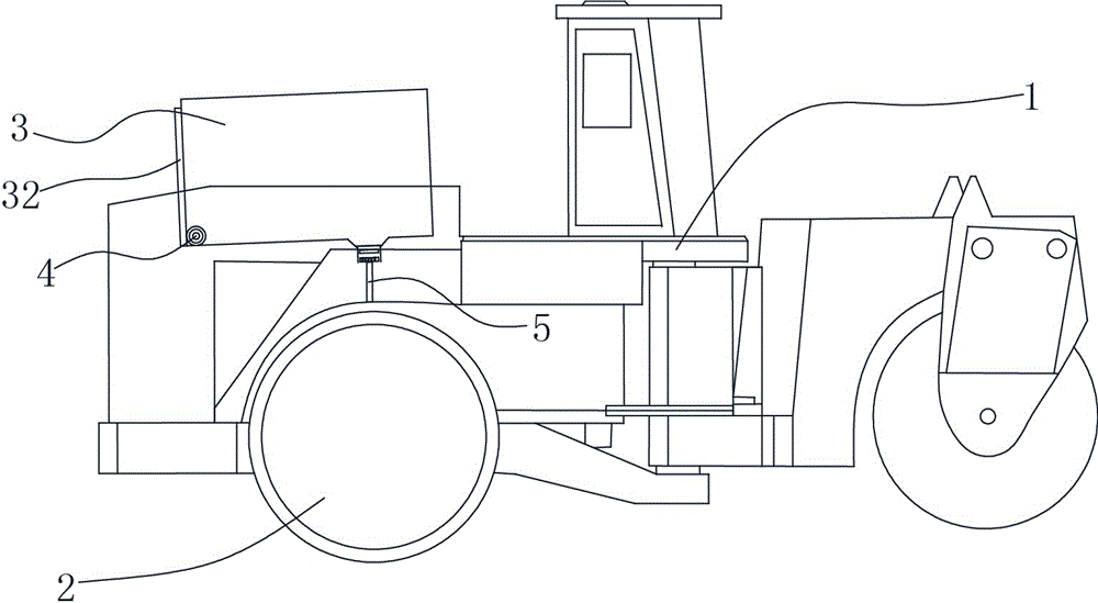
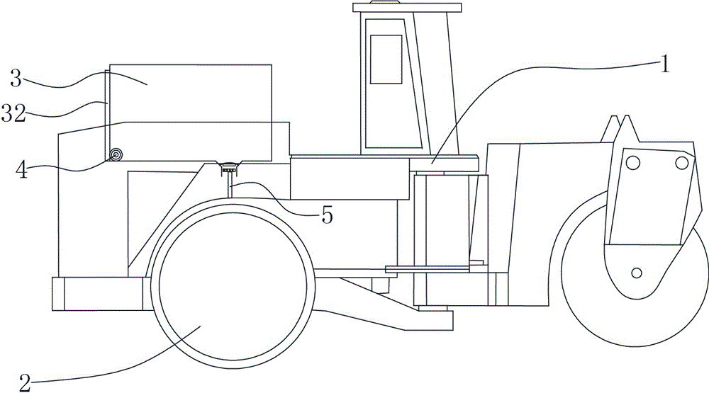
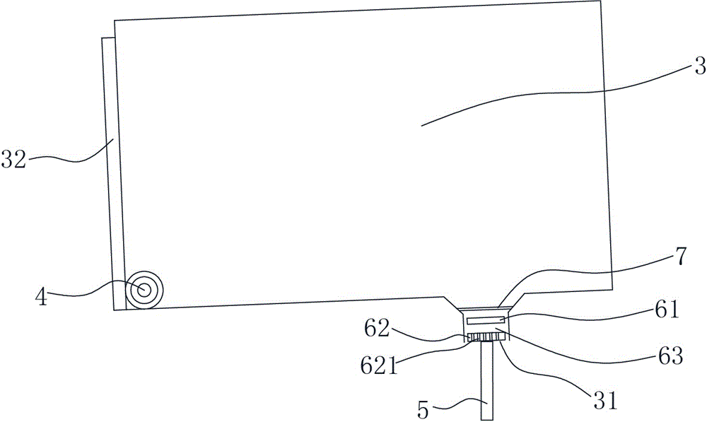
[0012] The present invention will be further described below in conjunction with the accompanying drawings and specific embodiments. Such as Figure 1 to Figure 5 As shown, a road roller that automatically adjusts the water output includes a road roller main body 1, a steel wheel 2, and a water tank 3 that sprays water to the steel wheel 2. The water tank 3 is provided with a water outlet 31, and the water outlet 31 is A plug 6 is formed to block the water outlet 31. An elastic member 7 (such as a rubber strip) is arranged above the plug 6. A water outlet 63 is provided in the middle of the plug 6. The water outlet 63 divides the plug into upper and lower parts. A plug 61 and a lower plug 62, the lower plug 62 is provided with several through holes 621, the lower part of the water outlet 31 is provided with a push rod 5, and the water tank 3 is also provided with a torsion spring 4.
[0013] In the above technical solution, a resistance plate 32 is formed on the outer wall of...
PUM
 Abstract
Description
Claims
Application Information